


- 107 -
4-3. PUH-5,8,10 (Side blow type)
4-3-1. Install
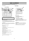
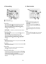
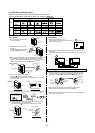
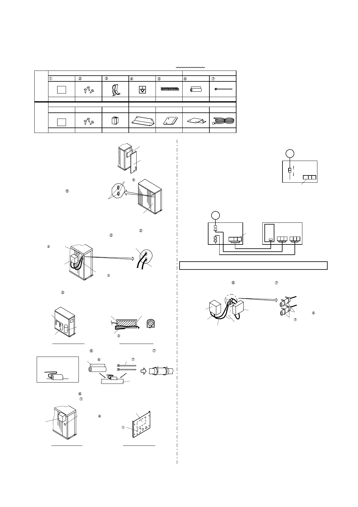
Accessory assy 1
Wiring sticker Earth stickerScrew
Spring
Grommet
Accessory assy 2Accessory assy 1
Use
Not
use
Attachment
Insert the thermistor
Thermistor Thermistor holder
Spring
ONLY PU(H)-7,8,10
Accessory assy 2
Pipe cover Band
1
Attachment Attachment
3111
13
Screw Connector Connector assy
9
1
1
12315
Thermistor position
Wiring sticker
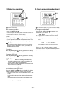
1. The service panel and control box
cover are removed.
2. Penetrate the knockout holes at
the pillar 3.
The grommet (2 pieces) install to
the hole for wiring in the pillar 3.
4. Confirm the thermistor holder position.
The spring insert in the thermistor holder.
The thermistor (black wiring) which is connected to the fan controller
is put in the holder.
3. Wiring from the fan controller is passed through the hole of procedure 2.
The thermistor and other wiring should use separate wiring hole.
The fan controller install to the pillar 3 with the screw (1 piece) and
install to the top panel with the screw (2 pieces).
6. The earth sticker and wiring sticker are put on an following place.
1. The earth sticker is put on the pillar 3.
2. The wiring sticker is put on the control box cover (inside).
Put a wiring stickerPut a earth sticker
1. Disconnect connector C11- C11.
The connector C11 removes to the motor side
and the control box side.
2. When the fan controller is installed, the connector is connected in the
control box.
The wiring from CN04 connect to the terminal block (F/C, N) in the control
box.
Please be careful, do not damage wires by the sheet metal edges or the fin, etc.
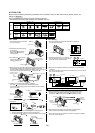
5. Please use the pipe cover (1 piece) and fix with the band (2 pieces).
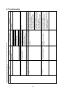
4-3-2. Wiring
3. After connect wiring, to prevent wiring being damaged with the pipe
header, the pipe cover (2 pieces) and band (4 pieces) are used.
In that time, never bundle the thermistor wiring with other wiring.
4. After wiring ends, the wiring is bundled with a remaining band.
Never bundle the thermistor and other wiring together.
5. Ensure there is not wiring mistake found, then only install the controller
box cover and service panel.
Please use the following parts during installation of fan controller.
There are two kinds of wiring sticker, please use writing as "W881927".
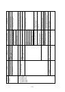
Service panel
Control box
cover
Earth sticker
Unit wiring sticker
Fan controller
wiring sticker
CN04
UVW L1 L2L3
MF2
Terminal block
Control box
Fan controller
C11
C11
MF2
Control box
C11
C11
Terminal block
Compressor
Accumulator
Grommet
Wiring hole
Fan controller
Thermistor wiring
only
Other wiring
Fan
controller
Fan
controller
Thermistor
wiring only
Other wiring
Pillar 3
Band
Pipe cover
Thermistor
wiring only
Other wiring
Pillar 3
Thermistor
holder position
Pipe cover Band
Pipe
The thermistor wiring is
bundled as follows before
the pipe cover is installed.
Install to the top panel.
(Screw 2 pieces)
Install to the pillar 3.
(Screw 1 piece)
51 N
F/C N
Control
box