


7
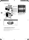
4-1.PURGINGPROCEDURESANDLEAKTEST
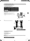
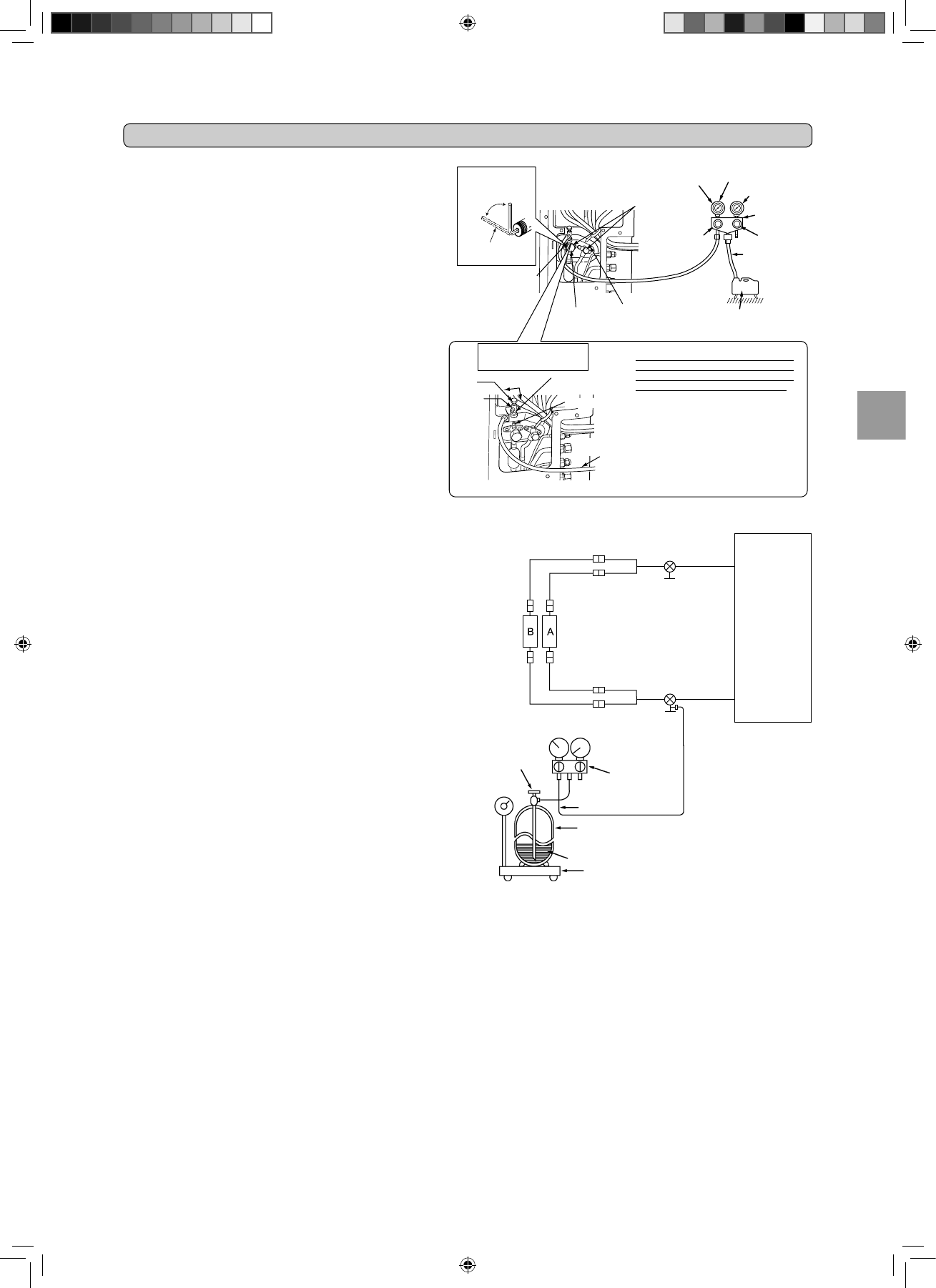
Stop valve
for GAS
Stop valve cap
(Torque 19.6 to
29.4 N•m, 200 to
300 kgf•cm, 15 to
22 ft
•lb)
Gauge manifold
valve(forR410A)
Compound pressure
gauge(forR410A)
–0.101MPa
[–760 mmHg
(-30in.Hg)]
Handle
Low
Handle High
Vacuum pump
(forR410A)
*Close
*Open
Hexagonal wrench
*4 to 5 turns
Stop valve
for LIQUID
4. PURGINGPROCEDURES,LEAKTEST,ANDTESTRUN
Pressure gauge
(forR410A)
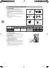
Precautions when using
the control valve
When attaching the control valve to
theserviceport,valvecoremayde-
form or loosen if excess pressure is
applied.Thismaycausegasleak.
Service port
Charge hose
(forR410A)
Body
Close
Open
Control
valve
A
When attaching the control valve to
the service port, make sure that the
valve core is in closed position, and
then tighten part A. Do not tighten
partAorturnthebodywhenvalve
core is in open position.
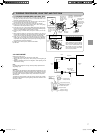
4-2.GASCHARGE
Perform gas charge to unit.
1 Connectgascylindertotheserviceportofstopvalve.
2 Performairpurgeofthepipe(orhose)comingfromrefrigerantgas
cylinder.
3 Replenishspeciedamountoftherefrigerant,whileoperatingtheair
conditioner for cooling.
Note:
Incaseofaddingrefrigerant,complywiththequantityspeciedforthe
refrigeratingcycle.
CAUTION:
Whenchargingtherefrigerantsystemwithadditionalrefrigerant,besure
touseliquidrefrigerant.Addinggasrefrigerantmaychangethecomposi
-
tionoftherefrigerantinthesystemandaffectnormaloperationoftheair
conditioner.Also,chargethesystemslowly,otherwisethecompressor
will be locked.
Tomaintainthehighpressureofthegascylinder,warmthegascylinder
withwarmwater[under40°C(140°F)]duringcoldseason.Butneveruse
nakedreorsteam.
Union
Stop valve
Liquid pipe
Union
Union
Union
Indoor
unit
Stop valve with
service port
Gas pipe
Refrigerant gas
cylinder
operating valve
(forR410A)
Gauge manifold
valve(forR410A)
Chargehose(forR410A)
Refrigerantgascylinder
for R410A with siphon
Electronic scale for
refrigerant charging
Refrigerant(liquid)
Outdoor
unit
1)Removeserviceportcapofstopvalveonthesideoftheoutdoorunit
gas pipe. (The stop valve will not work in its initial state fresh out of
thefactory,totallyclosedwithcapon.)
2)Connectgaugemanifoldvalveandvacuumpumptoserviceportof
stop valve on the gas pipe side of the outdoor unit.
3)Runthevacuumpump.(Vacuumizeformorethan15minutes.)
4)Checkthevacuumwithgaugemanifoldvalve,thenclosegauge
manifold valve, and stop the vacuum pump.
5)Leaveasitisforoneortwominutes.Makesurepointergaugemani
-
foldvalveremainsinthesameposition.Conrmthatpressuregauge
shows–0.101MPa[Gauge][–760mmHg(-30in.Hg)].
6)Removegaugemanifoldvalvequicklyfromserviceportofstop
valve.
7)Afterrefrigerantpipesareconnectedandevacuated,fullyopenall
stop valves on both sides of gas pipe and liquid pipe. Operating with
-
outfullyopeninglowerstheperformanceandthiscausestrouble.
8)Referto1-4.,andchargetheprescribedamountofrefrigerantif
needed.Besuretochargeslowlywithliquidrefrigerant.Otherwise,
compositionoftherefrigerantinthesystemmaybechangedandaf
-
fect performance of the air conditioner.
9)Tightencapofserviceporttoobtaintheinitialstatus.
10)Leaktest
Service port cap
(Torque 13.7 to
17.7 N•m, 140 to
180 kgf
•cm, 10 to
13 ft
•lb)
Charge hose
(forR410A)
JG79A039H01_En.indd 7 5/9/2008 2:23:44 PM