


7272
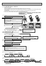
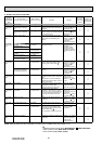
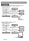
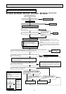
11-5. TROUBLESHOOTING FLOW
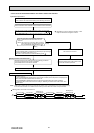
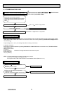
Is the voltage balanced?
Disconnect the connector between
compressor and the intelligent power module
(IPM)/ IGBT module (IC700)/ power module
(IPM). 1.
Replace the inverter P.C. board.
Check the voltage between terminals.
Check the compressor.
See 11-5.
“Check of compressor”.
No
Yes
See 11-5. “Check of open phase”.
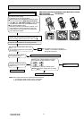
A How to check inverter/compressor
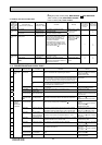
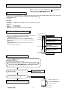
Refer to 11-5. “Check of compressor
operation time”.
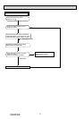
Does the compressor operate continuously?
Refer to 11-5. “Check of compressor start failure”.
OK.
No
Yes
Refer to 11-5. “Check of compressor
winding”.
Is the compressor normal?
Replace the compressor.
No
Yes
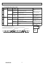
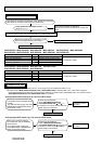
B Check of open phase
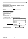
C Check of compressor
● With the connector between the compressor and the intelligent power module (IPM)/ IGBT module (IC700)/ power module
(IPM) disconnected, activate the inverter and check if the inverter is normal by measuring the balance of voltage between
the terminals. 1.
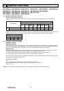
Output voltage is 50 - 130 V. (The voltage may differ according to the tester.)
<< Operation method>>
Start cooling or heating operation by pressing EMERGENCY OPERATION switch on the indoor unit. (TEST RUN OPERA-
TION: Refer to 8-3.)
<<Measurement point>>
At 3 points
BLK (U)-WHT (V)
BLK (U)-RED (W)
WHT(V)-RED (W)
NOTE: 1. Output voltage varies according to power supply voltage.
2. Measure the voltage by analog type tester.
3. During this check, LED of the inverter P.C. board fl ashes 9 times. (Refer to 11-6.1.)
Measure AC voltage between the lead wires at 3 points.
1.
Intelligent power module (IPM): MUZ-GE25VA -
A1
, MUZ-GE35/50VA
IGBT module (IC700): MUZ-GE60/71/80VAD
Power module (IPM): Other models
OBH532E