


40
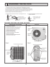
OPERATING PROCEDURE
PHOTOS
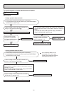
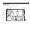
2. Removing the inverter assembly, P.C. board and
power board
(1) Remove the top panel, cabinet, service panel and the back
panel. (Refer to 1.)
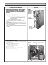
(2) Disconnect the following connectors;
<Electronic control P.C. board>
CN931 and CN932 (Fan motor)
CN795 (LEV)
CN661 (Discharge temperature thermistor, defrost
thermistor (MUZ) and outdoor heat exchanger
temperature thermistor)
CN663 (Ambient temperature thermistor)
CN681 (High pressure switch) (MUZ)
<Noise filter P.C. board>
CN912 (4-way valve) (MUZ)
<Compressor>
<Reactor>
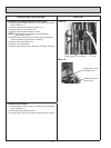
(4) Remove the screws fixing the relay panel.
(5) Remove the inverter assembly.
(6) Disconnect all connectors and lead wires on the electronic
control P.C. board.
(7) Remove the electronic control P.C. board from the inverter
assembly.
(8) Remove the screws fixing the power board assembly.
(9) Disconnect all connectors and lead wires on the power
board.
(10)
Remove the power board from the inverter assembly.
(11)
Disconnect all connectors and lead wires on the noise filter
P.C. board.
(12)
Remove the noise filter P.C. board from the inverter
assembly.
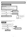
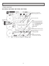
3. Removing R.V. coil (MUZ)
(1) Remove the top panel, cabinet, service panel and the back
panel. (Refer to 1.)
(2) Disconnect the following connectors;
<Noise filter P.C. board>
CN912 (4-way valve)
(3) Remove the R.V. coil. (Photo 9)
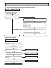
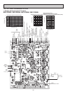
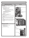
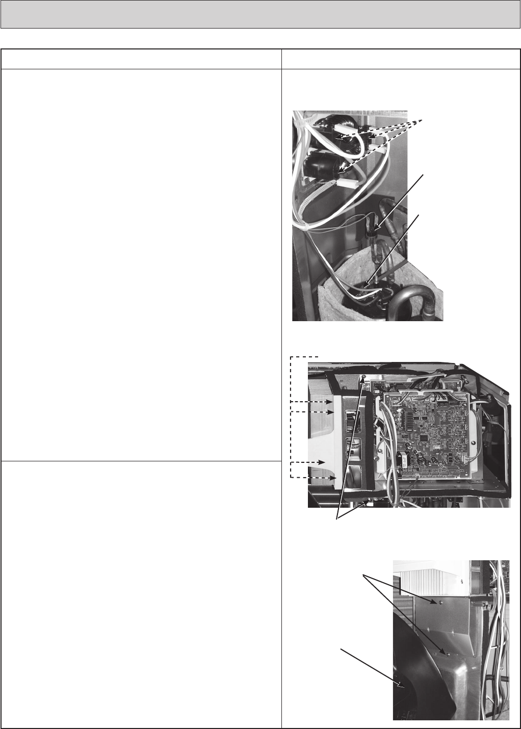
Photo 4
Screws of the relay panel
Screws of the power board assembly
Photo 5 (Inverter assembly)
Screws of the reactor
HPS
Discharge temperature
thermistor
Photo 6
Screws of the
relay panel
Propeller