11
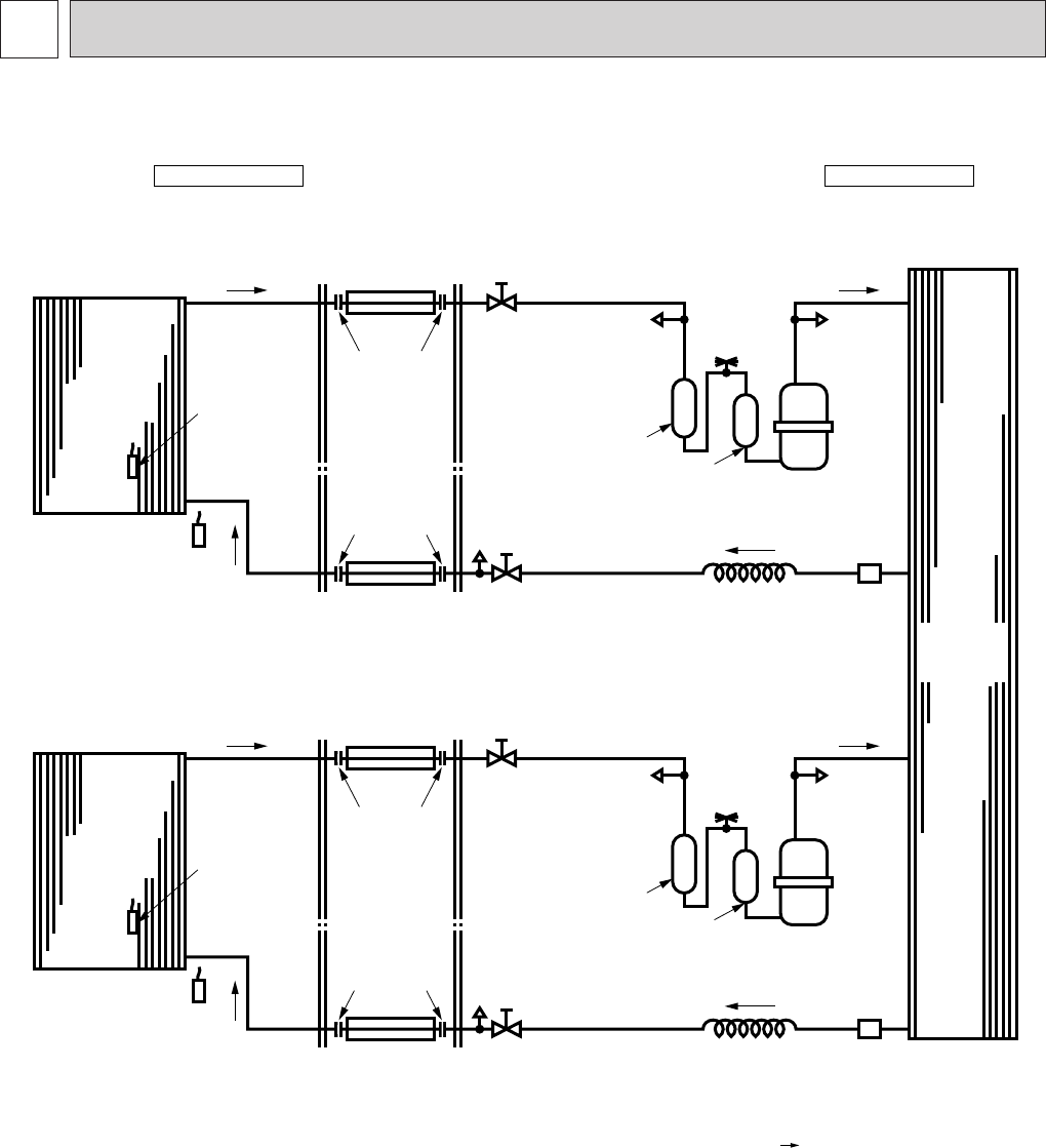
8 REFRIGERANT SYSTEM DIAGRAM
MS09NW✕ 2/MUM18NW
Unit : inch
Indoor unit Outdoor unit
Indoor heat
exchanger
Indoor coil
thermistor
RT12
Room
temperature
thermistor
RT11
Flared
connection
Flared
connection
Refrigerant pipe [1/4
(Option)
(with heat insulator)
Ball valve
with service port
Refrigerant pipe [3/8
(Option)
(with heat insulator)
Ball valve
Service
port
Service
port
Accumulator
Muffler
Fusible
plug
Compressor
OD0.12oID0.055o23-5/8
Capillary tube
Strainer
Indoor heat
exchanger
Indoor coil
thermistor
RT12
Room
temperature
thermistor
RT11
Flared
connection
Flared
connection
Refrigerant pipe [1/4
(Option)
(with heat insulator)
Ball valve
with service port
Refrigerant pipe [3/8(Option)
(with heat insulator)
Ball valve
Service
port
Service
port
Accumulator
Muffler
Fusible
plug
Compressor
OD0.12oID0.055o23-5/8
Capillary tube
Strainer
Flow of refrigerant
Outdoor
heat
exchanger
OB202-1.qxp 26/9/97 11:07 AM Page 11


