


10
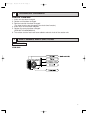
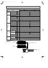
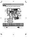
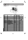
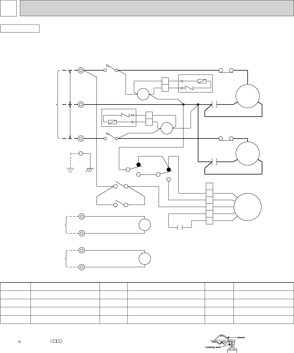
7 WIRING DIAGRAM
OUTDOOR
MODEL MUM18NW WIRING DIAGRAM
F
NR
115V
34
BLK
BRN
2
1
BLU
GRY
N
❈
❈
❈
BLK
ORN
YLW
X2
X1
2
2
6
6
4
4
YLW
BLU
L2
BLU
RED
TB3
TO INDOOR
UNIT No.B
CONNECTING
WIRES
DC12V
2
52
C2
GRY
VLT
2
1
TO INDOOR
UNIT No.A
CONNECTING
WIRES
DC12V
2
1
52
C1
ORN
BRN
2
1
TB2
X2
X1
5
5
3
3
WHT
RED
RED
GROUND
C3
7
7
8
8
X1
X2
52C1
52C2
4 3
BLK
TB1
L1
115V
POWER
SUPPLY
208/230V
1phase
3wires
60Hz
YLW
GRY
NR
F
GRY
WHT WHT
BLK
BRN
2
1
2
1
BLK
RED
WHT
2
1
S
MC1
MC2
MF
51C1
C1
BLK
WHT
BLK
BLK
RED
WHT
BLK
RED
BLK
GRY
1
5
4
3
YLW
ORN
RED
YLW
BLK
WHT
ORN
R
R
S
C
C
1
1
2
2
C2
51C2
❈
❈
❈
❈
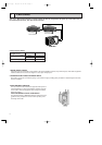
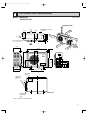
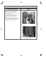
1.Slide the sleeve.
2.Pull the wire while
pushing the locking
lever.
NOTE:1. Use copper conductors only (For field wiring).
2. Symbols below indicate.
: Terminal block, : Connector
3. “❈”shows the terminals with a lock mechanism, so they cannot be removed when you pull
the lead wire.
Be sure to pull the wire by pushing the locking lever (projected part) of the terminal with a finger.
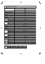
SYMBOL NAME SYMBOL NAME SYMBOL NAME
C1,2
COMPRESSOR CAPACITOR
MF
FAN MOTOR(INNER THERMOSTAT)
51C1,2
OVERCURRENT RELAY
C3 FAN MOTOR CAPACITOR NR VARISTOR 52C1,2
COMPRESSOR CONTACTOR
F FUSE(3.0A) TB1~3 TERMINAL BLOCK
MC1,2 COMPRESSOR X1,2 FAN MOTOR RELAY
OB202-1.qxp 26/9/97 11:07 AM Page 10