


8
6
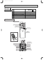
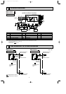
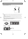
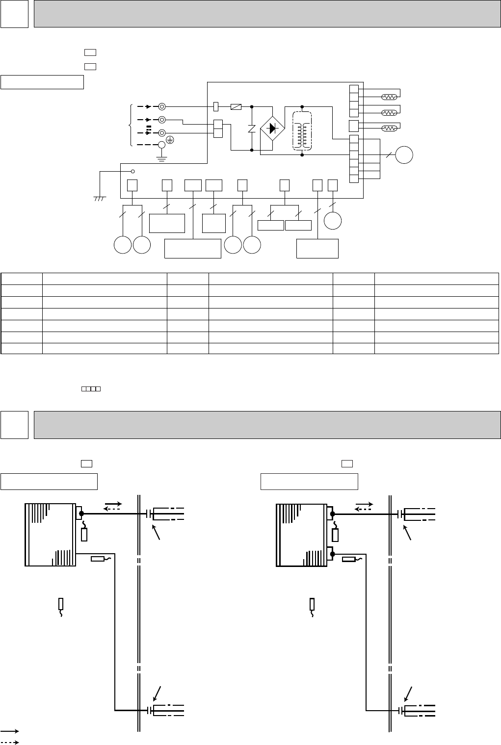
WIRING DIAGRAM
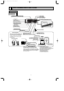
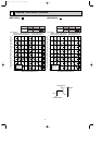
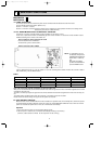
REFRIGERANT SYSTEM DIAGRAM
7
MSZ-FA25VA -
E1
Indoor
heat
exchanger
Flared connection
Room temperature
thermistor
RT11
Indoor coil
thermistor
RT13(sub)
Flared connection
Refrigerant flow in cooling
Refrigerant flow in heating
Refrigerant pipe [9.52
(with heat insulator)
Refrigerant pipe [6.35
(with heat insulator)
Indoor coil
thermistor
RT12(main)
Indoor
heat
exchanger
Flared connection
Room temperature
thermistor
RT11
Indoor coil
thermistor
RT13(sub)
Flared connection
Refrigerant pipe [9.52
(with heat insulator)
Refrigerant pipe [6.35
(with heat insulator)
Indoor coil
thermistor
RT12(main)
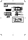
INDOOR UNIT
Unit : mm
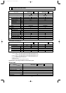
INDOOR UNIT
MODELS WIRING DIAGRAM
SYMBOL
DB111
F11
MF
MP
MT
MV1
SYMBOL
MV2
NR11
PLASMA_A
PLASMA_D
RR
RT11
SYMBOL
RT12
RT13
T111
TB
NAME
DIODE STACK
FUSE (T3.15AL250V)
INDOOR FAN MOTOR
FRONT PANEL DRIVING MOTOR
i-see Sensor MOTOR
VANE MOTOR (HORIZONTAL)
NAME
VANE MOTOR (VERTICAL)
VARISTOR
PLASMA AIR PURIFYING FILTER UNIT
PLASMA DEODORIZING FILTER UNIT
i-see Sensor
ROOM TEMPERATURE THERMISTOR
NAME
INDOOR COIL THERMISTOR (MAIN)
INDOOR COIL THERMISTOR (SUB)
TRANSFORMER
TERMINAL BLOCK
NOTE:1. About the outdoor side electric wiring refer to the outdoor unit electric wiring diagram for servicing.
2. Use copper conductors only. (For field wiring)
3. Symbols below indicate.
/: Terminal block, : Connector
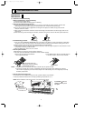
MSZ-FA25VA -
MSZ-FA35VA -
E1
E1
MSZ-FA35VA -
E1
INDOOR UNIT
1
2
3
4
S2
8
230V~
BLU
INDOOR ELECTRONIC
CONTROL P.C. BOARD
33
PLASMA_DPLASMA_A
SAFETY DEVICE
(PLASMA UNIT)
MP
RR
5
4
MT
SW P.C.
BOARD
POWER MONITOR
RECEIVER P.C. BOARD
INTERLOCK
SWITCH(FAN)
5
5
MV2
MV1
TO OUTDOOR
UNIT
CONNECTING
BLK
RED
S3
TB
TAB3
DB111
NR11
F11
5
6
4
2
5
CN
1U1
2
CN
1T2
CN
1T1
CN
110
3
LD
105(T)
LD
101(A)
12-24V
RT13
2
1R1
CN
GRN
LD104
CN201
2
1
151
CN
T111
RED
WHT
111
CN
CN
112
CN211
BLU
YLW
BLK
MF
RT11
RT12
1
3
5
S1
OB371_--1qxp 05.1.17 12:50 Page 8