


30
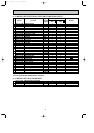
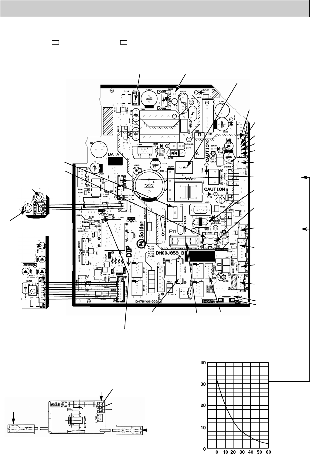
Indoor coil thermistor [RT12 (MAIN), RT13 (SUB)]
Room temperature thermistor (RT11)
Temperature (:)
Resistance (k")
MSZ-FA25VA - MSZ-FA35VA -
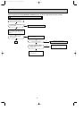
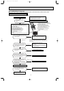
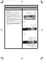
Indoor electronic control P.C. board
E1E1
Release of Auto restart
function
Solder the Jumper wire
to JR07.
(Refer to 8-3.)
12V DC
Varistor
(NR11)
5V DC
Room temperature
thermistor (CN111)
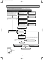
Indoor coil thermistor
RT12(MAIN)
12
RT13(SUB)
34
(CN112)
Timer short mode
point JPG, JPS
(Refer to 8-1.)
Horizontal and
Vertical vane
motor(CN151)
}
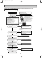
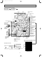
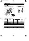
9-7. Test point diagram and voltage
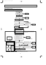
SW P.C. Board
Power monitor
receiver P.C.
board.
i-see Sensor
(CN110)
Fuse
(F11)
Front panel
driving motor
(CN1U1)
Safety device(Plasma unit)
(CN1T2)
Plasma deodorizing/air
purifying filter units
(CN1T1)
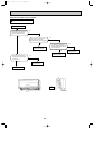
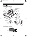
CN2011
(Used for check of con-
ducting of thermal fuse)
Interlock switch(Fan)
(CN1R1)
6(+)0V DC or 15V DC
5(+)3-6V DC
415
V DC
3(-) Fiducial terminal of
cathode side on measur-
ing high-voltage DC
1311V DC
Cement resistance
(R111)
Indoor fan motor
(CN211)
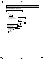
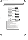
1DC 2.5V during PLASMA
AIR PURIFYING/PLASMA
DEODORIZING operation
3DC 12.5V during PLASMA
AIR PURIFYING/PLASMA
DEODORIZING operation
2GND
CN1
High-voltage lead wire
(Red)
Standard lead wire
(Green)
Plasma power P.C. board
WASH reset
switch(SW2)
Emergency
operation
switch(SW1)
230V AC
Power supply input
{
OB371_--1qxp 05.1.17 12:50 Page 30