


4-4. EXPLANATION TO THE USER
• Using the OPERATING INSTRUCTIONS, explain to the user how to use the
air conditioner (the remote controller, removing the air filters, placing or remov-
ing the remote controller from the remote controller holder, cleaning methods,
precautions for operation, etc.)
• Recommend that the user read the OPERATING INSTRUCTIONS carefully.
Caution:
• After test run or remote signal reception check, turn off the unit with the
E.O. SW or the remote controller before turning off the power supply. If this
procedure is not performed, the unit will automatically begin operation when
power supply is resumed.
To the user
• After installing the unit, explain to the user about auto restart function.
• If auto restart function is unnecessary, it can be deactivated. Consult the
service representative to deactivate the function. Refer to the service man-
ual for details.
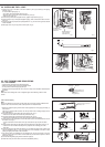
4-2. TEST RUN
1) Insert power supply plug into the power outlet and/or
turn on the breaker.
2) Press the E.O. SW once. Test run will be performed
for 30 minutes. If the left operation indicator light blinks
every 0.5 seconds, inspect the indoor/outdoor unit con-
necting wire (A). After the test run, emergency COOL
mode (75ºF [24ºC] COOL) will start.
3) To stop operation, press the E.O. SW several times
until all LED lamps turn off. Refer to operating instruc-
tions for details.
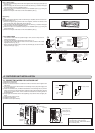
Checking the remote (infrared) signal reception
Press the ON/OFF button on the remote controller and listen for an audible indicator
from the indoor unit. Press the ON/OFF button again to turn the air conditioner off.
• Once the compressor stops, the restart preventive device operates so the compres-
sor will not operate for 3 minutes to protect the air conditioner.
4-3. AUTO RESTART FUNCTION
This product is equipped with an auto restart function. When the power supply is cut off
during operation, such as during blackouts, the function automatically starts opera-
tion in the previous setting once the power supply is resumed. (Refer to the operating
instructions for details.)
5-3. PUMPING DOWN
When relocating or disposing of the air conditioner, pump down the system following the
procedure below so that refrigerant is not released into the atmosphere.
1) Connect the gauge manifold valve to the service port of the stop valve on the gas
pipe side of the outdoor unit.
2) Fully close the stop valve on the liquid pipe side of the outdoor unit.
3) Close the stop valve on the gas pipe side of the outdoor unit almost completely so
that it can be easily closed fully when the pressure gauge shows 0 MPa [Gauge] (0
lbf/in.
2
[0 kgf/cm
2
]).
4) Start the emergency COOL operation.
To start the emergency operation in COOL mode, disconnect the power supply plug
and/or turn off the breaker. After 15 seconds, connect the power supply plug and/or
turn on the breaker, and then press the E.O. SW once. (The emergency COOL op-
eration can be performed continuously for up to 30 minutes.)
5) Fully close the stop valve on the gas pipe side of the outdoor unit when the pressure
gauge shows 0.05 to 0 MPa [Gauge] (approx. 7.25 to 0 lbf/in
2
[0.5 to 0 kgf/cm
2
]).
6) Stop the emergency COOL operation.
To stop operation, press the E.O. SW several times until all LED lamps turn off. Refer
to operating instructions for details.
5. RELOCATING THE UNIT / MAINTENANCE
HEAD OFFICE: TOKYO BLDG., 2-7-3, MARUNOUCHI, CHIYODA-KU, TOKYO
100-8310, JAPAN
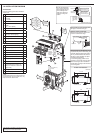
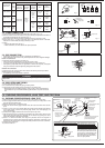
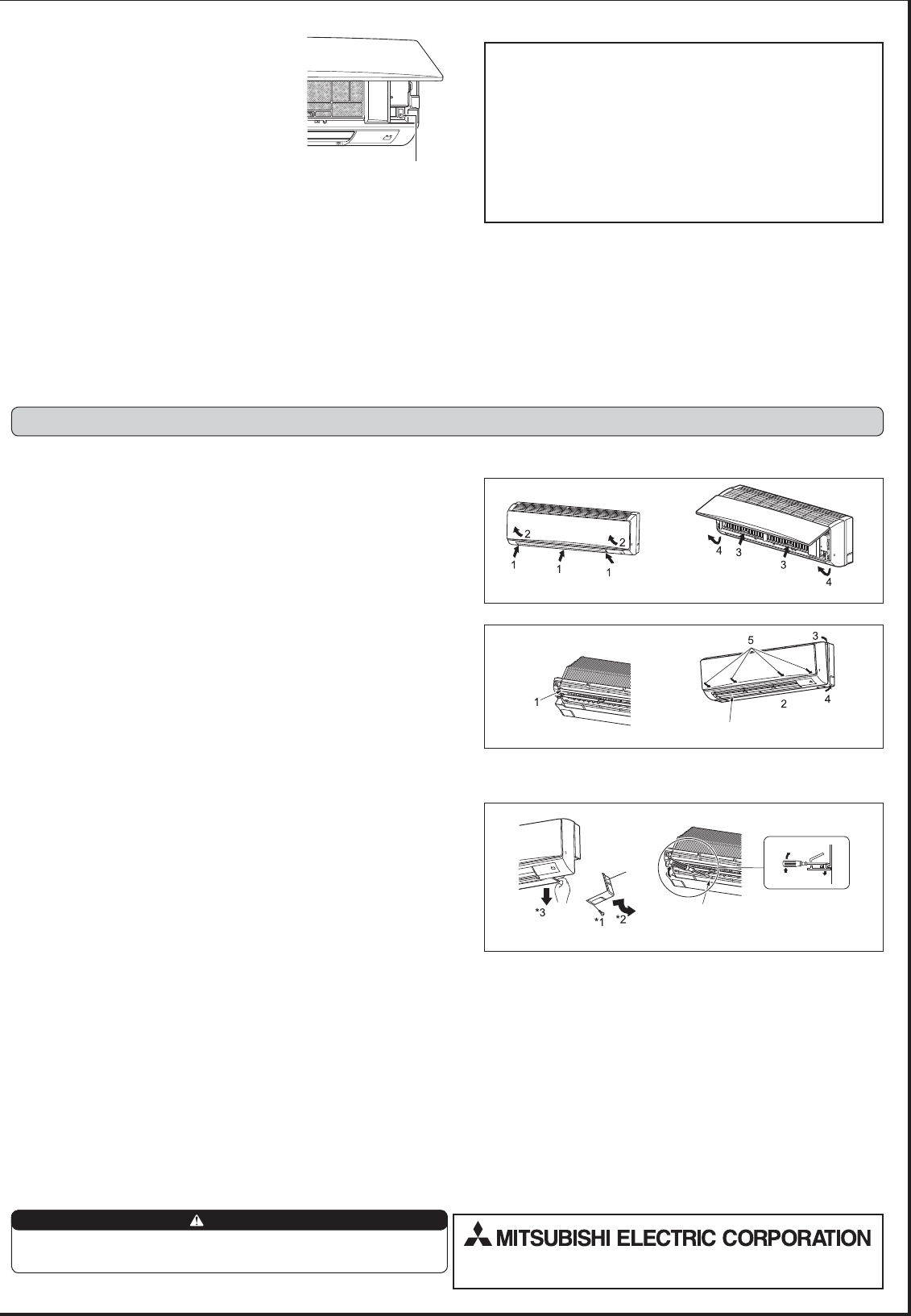
5-1. REMOVING AND INSTALLING THE PANEL ASSEMBLY
Removal procedure (Fig. 1, 2)
1) Remove the three screws that attach the panel assembly.
2) Open the front panel.
3) Remove the two screws that attach the panel assembly.
4) Remove the panel assembly. Be sure to remove its bottom end first.
5-2. REMOVING THE INDOOR UNIT
Remove the bottom of the indoor unit from the installation plate. (Fig. 1, 2)
• Remove the panel assembly. (Refer to 5-1)
• Insert flat screwdrivers into the square holes at the left and right bottom of the indoor
unit and push them up; the bottom of the indoor unit goes down and the hooks are
released.
*1 Remove the screw.
*2 Remove the tab of corner box from the indoor unit, and pull the corner box.
*3 Pull the indoor unit to remove.
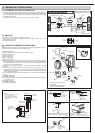
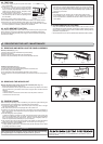
Installation procedure (Fig. 3, 4)
1) Point the horizontal vane slightly downward.
2) Attach the bottom of the panel assembly under the horizontal vane.
3) Fit in the top of the panel assembly.
4) Fit in the bottom of the panel assembly and tighten it using screws.
5) Push the section of the front panel marked by the arrows to close the front panel se
-
curely.
Emergency operation switch
(E.O. SW)
Fig. 3
Horizontal vane
Fig. 4
Square hole
Push
Lower
Corner box
Fig. 1 Fig. 2
Fig. 1 Fig. 2
When pumping down the refrigerant, stop the compressor before disconnecting
the refrigerant pipes. The compressor may burst if air etc. get into it.
WARNING