


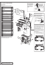
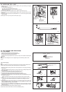
Outdoor unit installation
2-13/16 in. (70
mm) or more/
5-1/8 in. (130 mm)
or more for left and
left back piping
(using spacer)
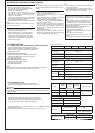
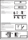
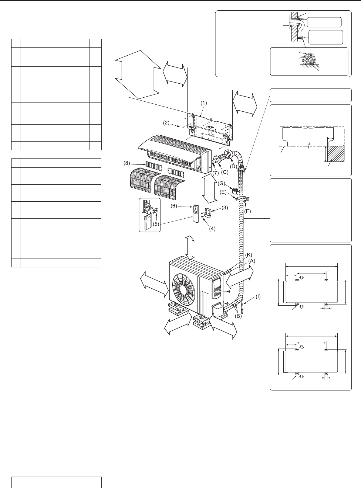
1-4. INSTALLATION DIAGRAM
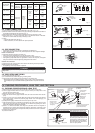
ACCESSORIES
Check the following parts before installation.
<Indoor unit>
(1) Installation plate 1
(2)
Attachment screws for the installa-
tion plate
4 × 25 mm
7
(3) Remote controller holder 1
(4)
Screws for the remote controller
holder
3.5 × 16 mm (Black)
2
(5) Battery (AAA) for (6) 2
(6) Wireless remote controller 1
(7)
Felt tape
(For left or left-rear piping)
2
(8) Air cleaning filter 2
(9) Charge nut 1
(10) L-joint 1
FIELD-SUPPLIED PARTS
(A)
Indoor/outdoor unit connecting wire *
1
(B) Extension pipe 1
(C) Wall hole sleeve 1
(D) Wall hole cover 1
(E) Pipe attachment strap
2 to 5
(F) Screw for (E) 4 × 20 mm
2 to 5
(G) Piping tape 1
(H) Putty 1
(I)
Drain hose
(or soft PVC hose, 19/32 in. [15
mm] inner diameter or hard PVC
pipe VP16)
1
(J) Refrigerant oil 1
(K) Power supply cord * 1
Units should be installed by licensed contractor
according to local code requirements.
* Note:
Place indoor/outdoor unit connecting wire (A)
and power supply cord (K) at least 3 ft. (1 m)
away from the TV antenna wire.
Unit: inch
Unit: mm
4-11/16 in.
(120 mm)
or more
Space for indoor unit working
Please leave the space as shown in the
picture for maintenance usage.
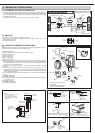
After the leak test, apply insulating mate-
rial tightly so that there is no gap.
Indoor unit
Wall hole
sleeve (C)
Cut off the
extra length.
Pipe attach-
ment strap
(E)
Use the wall hole sleeve
(C) to prevent indoor/out-
door connecting wire (A)
from contacting metal
parts in the wall and to
protect the wiring from
rodents.
Wall hole cover (D)
Seal the wall hole
gap with putty (H).
Attach the pipe to
wall with pipe at-
tachment strap (E).
Attachment screw (F)
33-1/16
14-3/16
19-11/16
Air inlet
3-15/16
15-14/32
13
Air outlet
4-3/8 x 13/16 slot 1-18/32
40
840
100 500
Air inlet
392
330
360
Air outlet
4-10 x 21 slot
When the piping is to be attached to a wall
comprised of tin plate or metal netting, use
chemically treated wooden piece 25/32 in.
(20 mm) or thicker between the wall and
the piping, or wrap insulation vinyl tape 7
to 8 turns around the piping.
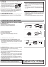
To use existing piping, perform COOL
operation for 30 minutes and pump down
before removing the old air conditioner.
Remake flare according to the dimension
for new refrigerant.
5/16 in. (7 mm)
or more
20 in. (500 mm)
or more
4 in.
(100 mm)
or more
4 in.
(100 mm)
or more
14 in.
(350 mm)
or more
20 in.
(500 mm)
or more
Note:
Do not
obstruct
the air
outlet.
Indoor unit
Installation
plate
Space
9-27/32 in. (250
mm) or more
4 in. (100 mm)
or more
8-11/16 in.
(220 mm)
or more