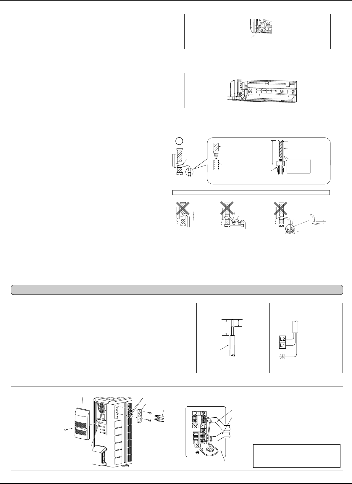
3-1. CONNECTING WIRES FOR OUTDOOR UNIT
1) Remove the service panel.
2) Remove the conduit cover.
3) Attach the conduit connector to conduit cover with lock nut then secure it against unit
with screws.
4) Connect ground wires of indoor/outdoor unit connecting wire (A) and power supply cord
(K) to the TB support.
5) Loosen the terminal screw, and attach indoor/outdoor unit connecting wire (A) from the
indoor unit correctly on the terminal block. Attach the wire to the terminal block securely
so that its core cannot be seen, and no external force affects the connecting section of
the terminal block.
6) Firmly tighten the terminal screws. After tightening, verify that the wires are tightly fas
-
tened.
7) Connect power supply cord (K).
8) Install the conduit cover.
9) Install the service panel securely.
Terminal block
to conduit cover
Power supply cord (K)
3. OUTDOOR UNIT INSTALLATION
Power supply cord (K)
Indoor/outdoor unit
connecting wire (A)
• Make ground wire a little longer than oth-
ers. (More than 1-3/8 in. [35 mm])
• For future servicing, leave some slack in
the connecting wires.
Lead
wire
5/8 in.
(15 mm)
1-3/8 in.
(35 mm)
Service panel
Lock nut
Conduit cover
Connector
Grounding
terminal
2-5-2. DRAIN PIPING
• If the extension drain hose has to pass through a room, be sure to wrap it with in-
VXODWLRQ¿HOGVXSSOLHG
• The drain hose should point downward for easy drain. (Fig. 1)
,IWKHGUDLQKRVHSURYLGHGZLWKWKHLQGRRUXQLWLVWRRVKRUWFRQQHFWLWZLWKD¿HOG
supplied drain hose (I). (Fig. 2)
• When connecting the drain hose to a hard vinyl chloride pipe, be sure to insert it
securely into the pipe. (Fig. 3)
Do not make drain piping as shown below.
Do not raise
Accumulated
drain water
Air
Waving
Water
leakage
Water
leakage
Water
leakage
Tip of drain
hose dipped
in water
Ditch
At least
1-31/32 in.
(50 mm)
gap
Downward
slope
Drain
hose
Soft hose I.D.
19/32 in.
(15 mm)
Drain hose
Hard vinyl chloride pipe
I.D. 1-3/16 in.
(30 mm)
Insert
securely
Different
diameter joint
27-9/16 in.
(70 cm)
or more
Fig. 1 Fig. 2 Fig. 3
Rear or bottom piping
3ODFHWKHUHIULJHUDQWSLSLQJDQGWKHGUDLQKRVHWRJHWKHUWKHQ¿UPO\DSSO\SLSLQJWDSH*
from the end.
2) Insert the piping and the drain hose into the wall hole sleeve (C), and attach the upper
part of the indoor unit on the installation plate (1).
3) Check if the indoor unit is attached securely on the installation plate (1) by moving the
unit to left and right.
4) Attach the lower part of the indoor unit into the installation plate (1).
Right piping
Note:
Before performing the following, make sure that wiring is completed, and the conduit cover
is installed. (Refer to 2-3.)
1) Place the refrigerant piping and the drain hose together, shift them to left side of the
XQLWDQGWKHQ¿UPO\DSSO\SLSLQJWDSH*IURPWKHHQG
2) Insert the piping and the drain hose into the wall hole sleeve (C), and attach the upper
part of the indoor unit on the installation plate (1).
3) Check if the indoor unit is attached securely on the installation plate (1) by moving the
unit to left and right.
4) Attach the lower part of the indoor unit into the installation plate (1).
Cut off in case of down-
ward piping.
TB support


