


NL
2
2
1
1
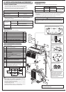
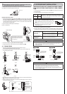
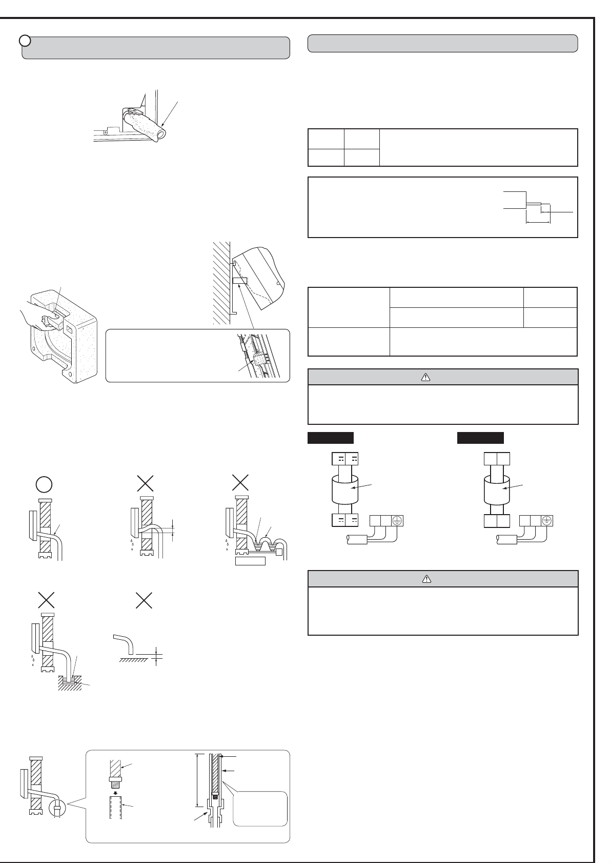
5. OUTDOOR UNIT INSTALLATION
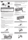
INDOOR/OUTDOOR UNIT CONNECTING WIRE CONNEC-
TION AND OUTDOOR POWER SUPPLY CORD CONNEC-
TION
•
Connect the indoor/outdoor unit connecting wire A from the indoor unit correctly on
the terminal block.
•
For future servicing, give extra length to connecting wire.
Rated
Voltage
Breaker
capacity
Connect to the supply terminals and leave a contact
separation of at least 3 mm at each pole to disconnect the
source power pole. (When the power switch is shut off, it
must disconnect all poles.)
230 V 15 A
O
Peel off both ends of connecting wire (extension wire).
When too long, or connected by cutting off the middle,
peel off power supply wire to the size as shown in the
right.
O
Be careful not to contact connecting wire with piping.
O
Make earth wire a little longer than the others.
(more than 35 mm)
35 mm
15 mm
•
For the power supply cord and the indoor/outdoor unit connecting wires, be sure to
use the ones in compliance with the standards.
•
Be sure to push the core until it is hidden and pull each cable to make sure that it is
not pulled up incomplete insertion may cause a risk of burning the terminal blocks.
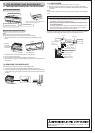
INDOOR UNIT INSTALLATION
•
Insert the drain hose into the wall hole sleeve C, and hook the upper part of indoor
unit on the installation plate 1. Then, move the unit to the very edge of the left side
for putting the piping easily in the back space of the indoor unit. After that, cut the part
of packing material (spacer assembly) to hook it on the back rib and lift the indoor
unit as shown in the fi gure below.
Power supply cord K
Indoor
terminal
block
Outdoor
terminal
block
Indoor/outdoor unit
connecting wire A
2-core 1.0 mm
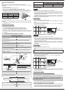
Downward
slope
Water
leakage
Do not raise.
Water
leakage
Accumulated
drain water
Waving
Water
leakage
Tip of drain
hose dipped
in water.
Ditch
Air
Soft hose
I.D.
15 mm
Drain
hose
Less than
50 mm gap
4
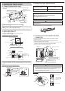
Insert the drain hose into the section to which the drain hose is
to be attached at the rear right of the indoor unit.
Insert the drain hose fully into the drain pan. Check if the hose is hooked securely to
the projection of its inserting part at the drain pan.
Drain hose
•
If the drain hose provided with the indoor unit is too short, connect it with drain hose
I that should be provided at your site. (Fig. 6)
•
When connecting the drain hose to the hard vinyl chloride pipe, be sure to insert it
securely into the pipe. (Fig. 7)
(Fig. 4) (Fig. 5)
(Fig. 1) (Fig. 2) (Fig. 3)
•
Connect the refrigerant piping with the extension pipe B.
•
Thrust the lower part of the indoor unit into the installation plate 1.
4-7 DRAIN PIPING
•
The drain hose should point downward for easy drain fl ow. (Fig. 1)
Do not make drain piping as shown in Fig. 2 to 5.
•
If the extension drain hose has to pass through a room, be sure to wrap it with
commercially sold insulation.
CAUTION
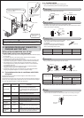
O Use care not to make mis-wiring.
O Firmly tighten the terminal screws to prevent them from loosening.
O After tightening, pull the wires lightly to confi rm that they do not move.
O If the connecting wire is incorrectly connected to the terminal block, the unit
does not operate normally.
WARNING
O A means for disconnection of the supply with an isolation switch, or similar
device, in all active conductors shall be incorporated in the fi xed wiring.
O Never cut the power cord and connect it to other wires.
It may cause a fi re.
Drain hose
70 cm or
more
Hard vinyl
chloride pipe
I.D. 30 mm
Be sure to insert
the drian hose
securely into the
pipe.
Different-
diameter joint
(Fig. 6) (Fig. 7)
Indoor/outdoor unit
connecting wire A
2-core 1.0 mm
Power supply cord K
Indoor
terminal
block
3 N
3
N
NL
Outdoor
terminal
block
MS type MSH type
Power supply cord
Specifi cation
3-core 1.5 mm
2
or more,
in conformity with Design 60245 IEC 57.
10 m or less
3-core 2.5 mm
2
or more,
in conformity with Design 60245 IEC 57.
15 m or less
Indoor and Outdoor
connecting wire
Specifi cation
Cable 2-core 1.0 mm
2
,
in conformity with Design 60245 IEC 57.
Securely attach the spacer assembly
in the concave part of the rib, taking
care its direction is correct as shown
in the fi gure right.
Spacer
Cut part of packing material (spacer assembly) to
hook it on the back rib.
Spacer assembly