


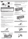
5
00 mm or m
ore
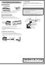
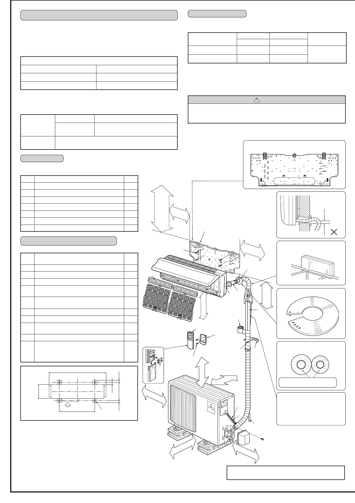
Be careful the
drain hose is not
raised.
Separate the 2 connecting pipes and
apply insulation individually.
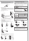
Decide the installation position using mark on the installation
plate indicating the indoor unit size as reference.
When the piping is to be attached to
a wall containing metals (tin plated)
or metal netting, use a chemically
treated wooden piece 20 mm or
thicker between the wall and the piping
or wrap 7 to 8 turns of insulation vinyl
tape around the piping.
Lock the catch.
Front
Piping can be directed towards rear,
right, downward, left or left-rear
directions.
Rear side
Right
Rear
Downward Left-rear
Left
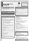
Units should be installed by licensed contractor according
to local code requirement.
Note:
When operating the air conditioner in low outside temperature,
be sure to follow the instructions described below.
•
Never install the outdoor unit in a place where its air inlet/outlet
side may be exposed directly to wind.
•
To prevent exposure to wind, install the outdoor unit with its
air inlet side facing the wall.
•
To prevent exposure to wind, it is recommended to install a
baffl e board on the air outlet side of the outdoor unit.
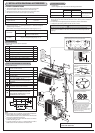
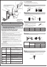
3.
INSTALLATION DIAGRAM & ACCESSORIES
FLARED CONNECTIONS
•
This unit has fl ared connections on both indoor and outdoor sides.
•
Remove the outdoor units valve cover, then connect the pipe.
•
Refrigerant pipes are used to connect the indoor and outdoor units.
•
Be careful not to crush or bend the pipe in pipe bending.
Limits
Pipe length 25 m max.
Height difference 10 m max.
No. of bends 10 max.
•
Refrigerant adjustment ... If pipe length exceeds 7 m, additional refrigerant
(R410A) charge is required.
(The outdoor unit is charged with refrigerant for pipe length up to 7 m.)
Pipe length
Up to 7 m No additional charge is required.
Exceeding 7 m
Additional charge is required.
(Refer to the table below.)
Refrigerant to
be added
20 g/m × (refrigerant piping length (m) -7)
ACCESSORIES
Check the following parts before installation.
<Indoor unit>
1
Installation plate 1
2
Installation plate fi xing screw 4 × 25 mm 7
3
Remote controller holder 1
4 Fixing screw for 3 3.5 × 16 mm (Black)
2
5
Battery (AAA) for remote controller 2
6
Wireless remote controller 1
7
Felt tape (Used for left or left-rear piping) 1
8
Air Cleaning fi lter 2
850mm
mm
0
9
2
mm013
500mm
mm81
mm
8
1
mm01
Slot
4-10 mm × 21 mm
Air outlet
350 mm or more
1
00 mm or more
A
I
5
4
B
6
E
F
G
D
H
C
7
1
2
1
2
0 mm
or more
72 mm or more
100 mm or more for left and left
back piping (using spacer)
200 mm or more
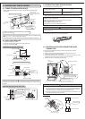
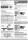
PIPING PREPARATION
1 Specifi cations
Use the refrigerant pipes that meet the following specifi cations.
Pipe
Outside diameter Insulation thickness
Insulation material
mm mm
For liquid 6.35 8
Heat resisting
foam plastic 0.045
specifi c gravity
For gas 12.7 8
• Use a copper pipe or a copper-alloy seamless pipe with a thickness of 0.8 mm.
Never use any pipe with a thickness less than 0.8 mm, as the pressure resistance
is insuffi cient.
2 Ensure that the 2 refrigerant pipes are insulated to prevent condensation.
3 Refrigerant pipe bending radius must be 100 mm or more.
CAUTION
Be sure to use the insulation of specifi ed thickness. Excessive thickness may
cause incorrect installation of the indoor unit and lack of thickness may cause dew
drippage.
8 mm thickness thermal insulation
plastic
7 mm or more
PART TO BE PROVIDED AT YOUR SITE
Optional extension pipe
A
Indoor/outdoor unit connecting wire
(2-core 1.0 mm
2
-2.0 mm
2
)
1
B
Extension pipe
1
C
Wall hole sleeve
1
D
Wall hole cover
1
E
Pipe fi xing band
(The quantity depends on the pipe length.)
2 to 5
F
Fixing screw for E 4 × 20 mm
(The quantity depends on the pipe length.)
2 to 5
G
Piping tape
1
H
Putty
1
I
Drain hose
(or soft PVC. hose, 15 mm inner dia.)
1
J
Refrigeration oil
1
K
Power supply cord (See the table in 5
INDOOR/OUTDOOR WIRE CONNECTION
AND OUTDOOR POWER SUPPLY CORD
CONNECTION for the cord size.)
1
3
Note: Do not obstruct
the air outlet.
100 mm or more
1
00 mm or more
8
K
1800 mm or more
from the fl oor