


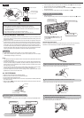
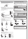
PURGING PROCEDURES
Leave as it is for one or two minutes. Make sure the pointer gauge manifold valve
remains in the same position. Confi rm that the pressure gauge shows–0.101 Mpa
[Gauge] (–760 mmHg).
Check the vacuum with the gauge manifold valve, then close the gauge manifold
valve, and stop the vacuum pump.
Run the vacuum pump. (Vacuumize for more than 15 minutes.)
Connect the gauge manifold valve and the vacuum pump to the service port of the
stop valve on the gas pipe side of the outdoor unit.
Remove the service port cap of the stop valve on the side of the outdoor unit gas
pipe. (The stop valve will not work in it initial state fresh out of the factory (totally
closed with cap on).)
Connect the refrigerant pipes (both liquid pipe and the gas pipe) between the indoor
and the outdoor unit.
Pipe length up to 7 m
No gas charge is needed.
Pipe length exceeding 7 m
Charge the prescribed amount
of gas. (refer to 3)
Remove the gauge manifold valve quickly from the service port of the stop valve.
After refrigerant pipes are connected and evacuated, fully open all stop valves on
both sides of gas pipe and liquid pipe.
Operating without fully opening lowers the performance and this causes trouble.
Tighten the cap to the service port to obtain the initial status.
Retighten the cap.
Leak test
6-4 PURGING PROCEDURES·LEAK TEST
PROCEDURE
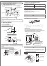
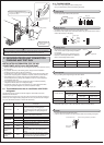
6-3 PIPE CONNECTION
Note:
Fasten a fl are nut with a torque wrench as specifi ed in the table below.
When fastened too tight, a fl are nut may broken after a long period and cause a leakage
of refrigerant.
1 Indoor unit connection
Connect both liquid and gas pipings to indoor unit.
•
Apply a thin coat of refrigeration oil J on the seat surface of pipe.
•
For connection fi rst align the center, then tighten the fi rst 3 to 4 turns of fl are nut.
•
Use tightening torque table below as a guideline for indoor unit side union joint section,
and tighten using two wrenches. Excessive tightening damages the fl are section.
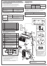
INSULATION AND TAPING
1 Cover piping joints with pipe cover.
2 For outdoor unit side, surely insulate every piping including valves.
3 Using piping tape G, apply taping starting from the entry of outdoor unit.
•
Stop the end of piping tape G with tape (with adhesive agent attached).
•
When piping have to be arranged through above ceiling, closet or where the temperature
and humidity are high, wind additional commercially sold insulation for prevention of
condensation.
2 Outdoor unit connection
Connect pipes to stop valve pipe joint of the outdoor unit in the same manner applied for
indoor unit.
•
For tightening, use a torque wrench or spanner and use the same tightening torque
applied for indoor unit.
Pipe diameter Tightening torque
mm N·m kgf·cm
ø6.35 13.7 to 17.7 140 to 180
ø12.7 49.0 to 56.4 500 to 575
Close
Open
Hexagonal wrench
Stop valve
Gauge manifold valve
Charge
hose
Stop valve
Liquid pipe
Hexagonal
wrench
Gas pipe
Caps
Stop valve
Service port
Vacuum pump
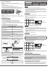
When attaching the control valve to the service port,
valve core may deform or loosen if excess pressure
is applied. This may cause gas leak.
When attaching the control valve to the service port,
make sure that the valve core is in closed position, and
then tighten part A. Do not tighten part A or turn the body
when valve core is in open position.
Precautions when using the control valve
Service port
Charge hose
Body
Close
Open
Control Valve
A
Tightening torque
N·m kgf·cm
Cap for service port 13.7 to 17.7 140 to 180
Cap for stop valve 19.6 to 29.4 200 to 300
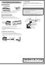
6-5 TEST RUN
• Before performing the test run, recheck for any wrong wiring.
Wrong wiring prevents normal operation or results in blown fuse disabling operation.
• The test run can be started by pressing EMERGENCY OPERATION switch. When
the EMERGENCY OPERATION switch is once pressed, the unit will start the test run
(continuous operation) for 30 minutes.
A thermostat does not work during this time. After 30 minutes the unit will start the
EMERGENCY OPERATION at a fi xed temperature setting of 24°C in COOL MODE.
• Perform test run in the following procedure.
MS type
• Press the EMERGENCY OPERATION switch.
1 Press it once, and after test run for 30 minutes the EMERGENCY COOL MODE
starts.
2 Press it once more, and the operation stops.
(The operation mode alternates between 1 and 2 every time the EMERGENCY
OPERATION switch is pressed.)
EMERGENCY
OPERATION switch
Mode
Operation Indicator lamp
1
COOL
(Light) (Off)
2
STOP
(Off) (Off)
• Before performing the test run, recheck any wrong wiring.
Wrong wiring prevents normal operation or results in blown fuse disabling operation.
• The test run can be started by pressing EMERGENCY OPERATION switch. When
the EMERGENCY OPERATION switch is once pressed, the unit will start the test run
(continuous operation) for 30 minutes.
A thermostat does not work during this time. After 30 minutes the unit will start the
EMERGENCY OPERATION at a fi xed temperature setting of 24°C in COOL MODE or
HEAT MODE.
• Perform test run in the following procedure.
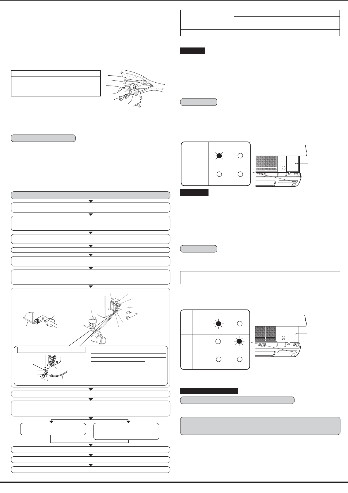
MSH type
PROCEDURE
• Press the EMERGENCY OPERATION switch.
1 Press it once, and after test run for 30 minutes the EMERGENCY COOL MODE
starts.
If the left side lamp of the operation indicator blinks every 0.5 seconds, inspect the
indoor/outdoor unit connecting wire A for mis-wiring.
2 Press it once more, and the EMERGENCY HEAT MODE starts.
3 Press it once more, and the operation stops.
(The operation mode changes in order of 1 ~ 3 every time the EMERGENCY
OPERATION switch is pressed.)
EMERGENCY
OPERATION switch
Mode
Operation Indicator lamp
1
COOL
(Light) (Off)
2
HEAT
(Off) (Light)
3
STOP
(Off) (Off)
• In starting the heating operation, indoor unit fan may not operate to prevent blowing
cool air. Please wait for a few minutes until the temperature of heat exchanger rises
and warm air blows out.
MS type and MSH type
Checking the remote (infrared) signal reception
Press the ON/OFF button on the remote controller and check that an electronic sound is
heard from the indoor unit. Press the ON/OFF button again to turn the air conditioner off.
If the indoor unit is operated with the remote controller, both the test
run and the emergency operation are released by commands from
the remote controller.
• Once the compressor stops, the restart preventive device operates so the compressor
will not operate for three minutes to protect the air conditioner.
6-6 EXPLANATION TO THE CUSTOMER
• Using the OPERATING INSTRUCTIONS, explain the following to the customer, how
to control temperature, how to remove the air fi lters, how to remove or put the remote
controller in the remote controller holder, how to clean, precautions for operation, etc.
• Recommend the customer to read the OPERATING INSTRUCTIONS carefully.