


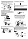
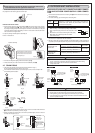
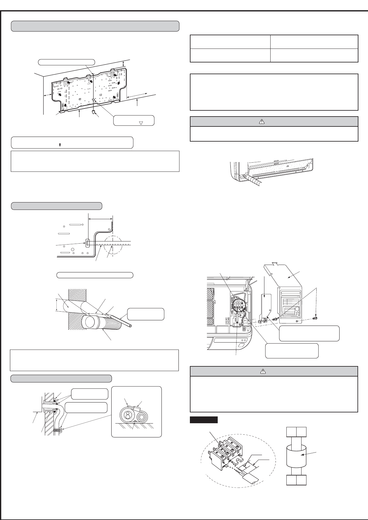
Wall hole
sleeve C
Indoor unit
Wall hole cover D
Seal the wall hole
gap with putty H.
Fix the pipe to wall with
pipe fi xing band E.
Cut off the
extra length. Pipe fi xing
band E
Fixing screw F
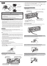
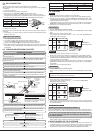
4-4 INDOOR AND OUTDOOR CONNECTING WIRE
CONNECTION
You can connect indoor/outdoor lead wire without removing the front panel.
1 Open the front panel.
2 Remove one screw holding the electrical cover, then remove the cover.
3 Remove the VA clamp and the cord clamp.
4 Pass the indoor/outdoor unit connecting wire from the back of the indoor unit and
process the end of the wire, then connect it to the terminal block.
5 Replace the fi xture and electrical cover securely.
15 mm
35 mm
3 N
3
N
Indoor terminal block
Indoor/outdoor unit
connecting wire A
2-core 1.0 mm
2
Outdoor terminal block
<Connection details>
Loosen terminal
screw.
Lead wire
Terminal
block
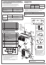
4. INDOOR UNIT INSTALLATION
4-1 FIXING OF INSTALLATION PLATE
•
Find a structural material (such as a stud) in the wall and fi x installation plate
horizontally.
2
00 mm or more
(off
the wall)
Plumb
12
0 mm or more
(off the wall)
Installation
plate 1
Align the plumb line
with the mark .
Bind the line to the center hole.
72 mm or more
100 mm or more for left
and left back piping (using
spacer)
To prevent the installation plate from vibrating, be sure to fi x the holes
as indicated by the arrows .
Installation
plate fi xing
screw 2
4 × 25 mm
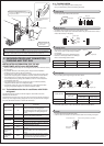
Insert the scale.
Installation plate 1
Hole of dia.
75 mm
Repeat the same procedure for the left hole.
Wall hole
75 mm dia.
(Indoor side)
(Wall hole cross section)
Wall thickness
One scale
Wall hole sleeve C
Cut with 1 extra
scale length.
Be sure to use wall hole sleeve C to prevent the outdoor connecting wires from
contacting with metal part in the wall and to prevent damage by rat in case the wall
is hollow.
Wall hole sealing and fi xing pipe to wall
Positioning of the holes on the wall
4-2 WALL HOLE DRILLING
1 Determine the wall hole position.
2 Drill a 75 mm hole so that outside can be lower than inside.
3 Insert the wall hole sleeve C.
When bolts recessed in the concrete wall are to be utilized, secure the installation plate
1 using 11 × 20 · 11 × 26 oval hole (450 mm pitch).
If the recessed bolt is too long, change it for a shorter one available in the market.
WARNING
O
Use the indoor/outdoor unit connecting wire that meets the Standards to connect
the indoor and outdoor units and fi x the wire to the terminal block securely so
that no external force is conveyed to the connecting section of the terminal block.
Incomplete connection or fi xing of the wire could result in a fi re.
O
Attach the VA clamp securely. If it is attached incorrectly, it could result in a fi re
or an electric shock due to dust, water, etc.
Align the scale with the line.
100 mm
4-3 CONNECTING WIRE SPECIFICATIONS
•
Use special room air conditioning circuit.
Power supply cord length
(Lead to left/Lead to right)
1 m/2 m
Indoor/outdoor unit connecting
wire Specifi cation
Cable 2-core 1.0 mm
2
, in conformity with
Design 60245 IEC 57.
•
Take out power supply cord from the left or right bottom corner of the indoor unit.
Connect to the power switch which has a gap of 3 mm or more when open to
interrupt the source power phase.
(When the power switch is shut off, it must interrupt all phases.)
(Rated Voltage/Frequency : 230 V/50 Hz)
(Input capacity Main switch/Fuse : 10 A)
(This plug has to be the one meets the Standards.)
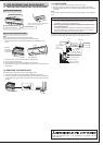
WARNING
Never cut the indoor and outdoor unit connecting wire and connect it to other wires.
It may cause a fi re.
Do not bundle the spare wire, but put it as shown below.
Indoor
terminal block
Securely push the wire into
the terminal block until no
part of its core is appeared.
Indoor/outdoor unit connecting wire A
ELECTRICAL COVER
Never fail to hook the left claw on
the wire fi xture to secure indoor/
outdoor unit connecting wire A.
Fixing screws
VA clamp
MSH type
1800 mm or more
from the fl oor