


6
7
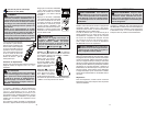
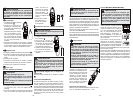
1. Set the Rotary Dial to
position.
2. Connect the red
test lead to the V
terminal and the
black test lead to
the COM termi-
nal.
3. Connect the red
test lead to the
positive (+) side
and black test
leads to the nega-
tive (-) side of the
circuit under test.
The reading is displayed. A reversed connection
is indicated as a negative value.
DANGER To avoid electrical shock:
Never make measurement on a circuit in
which voltage over DC600V exists.
Do not use with the Battery Cover removed.
Keep fi ngers away from jaws during mea-
surements.
DC Voltage
Resistance/Continuity/Capacitance
Measurements
DANGER
To reduce the risk of electric shock for
Resistance, Continuity, and Capacitance
measurements, never use the meter on an
energized circuit. Make sure a capacitor is
fully discharged before touching or attempt-
ing to make a measurement.
Do not use with the Battery Cover removed.
Resistance
1. Set the Rotary Dial to
position.
2. Connect the red test
lead to the V ter-
minal and the black
test lead to the COM
terminal.
Confi rm “OL” is indi-
cated on the display,
and then short-circuit
the tips of test leads
to make the indica-
tion zero.
3. Connect the test
leads to both ends of the resistor under test.
4. The reading is displayed.
CAUTION
After shorting the test leads, the displayed
value may not be zero due to the resistance
of test leads themselves.
Continuity
1. Set the Rotary Dial to
position.
2. Connect the red test lead
to the V terminal and the
black test lead to the COM
terminal.
Confi rm “OL” is indicated on
the display, and then short-
circuit the tips of test leads
to make the indication zero.
A buzzer will sound.
3. Connect the test leads to
both ends of the conductor
under test. If the resistance under test is 35 ±10
or 25 or less, the buzzer will sound.
Capacitance
1. Set the Rotary Dial to position.
2. Connect the red test lead to the V terminal and
the black test lead to the COM terminal.
3. Discharge capacitor.
4. Connect the test leads to both ends of the capaci-
tor under test.
5. The reading is displayed.
DC Current (Cat. No. 2236-20 only)
DANGER To avoid electrical shock:
Never make measurement on a circuit in
which voltage over AC600V exists.
Do not use with the Battery Cover removed.
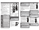
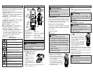
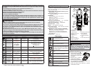
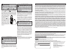
1. Set the Rotary Dial to
position. DC mark
is displayed.
2. Connect the red test
lead to the V ter-
minal and the black
test lead to the COM
terminal. Contact the
red test lead to the
fl ame sensor probe
and the black test
lead to the control
module.
3. Turn on the heating unit. The reading is dis-
played.
Flame
sensor
probe
Control
Module
1. Set the Rotary Dial to
position.
2. Connect the K-type Tem-
perature Probe to the input
terminal. The positive (+)
side of Probe should be
connected to V.
3. Place the probe sensor in
the desired location.
4. The reading is displayed.
CAUTION
The Data Hold readings are released when the
meter enters Sleep Mode.
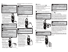
Worklight LED ON/OFF
To turn the light on and off, press the button.
HOLD Key
Data Hold Function - Freezes the value on the
display. Press the “HOLD” button to freeze the
reading. The reading will be held regardless of
subsequent variation in input. HOLD is displayed
with the reading. To exit Data Hold mode, press the
HOLD button again.
WARNING
Never connect the Temperature Probe to an
energized circuit.
CAUTION
When the Rotary Dial is set to , the room
temperature should be displayed. If anything
else is displayed, something may be wrong
with the meter. Stop using the meter imme-
diately.
Sleep Mode
The clamp meter is automatically powered off in
about 20 min after the last Rotary Dial or button
operation. To reset, rotate the Rotary Dial to OFF.
If the display is still blank when a new Rotary Dial
setting is selected, replace the batteries.
The sleep mode is disabled when the MIN/MAX
function is selected.
The clamp meter does use battery power in sleep
mode. Be sure to switch the tool to OFF to conserve
battery power.
Temperature (Cat. No. 2236-20 only)
DANGER
The LED may not be displayed due to instal-
lation condition of electrical circuit or equip-
ment. Never touch the circuit under test to
avoid possible danger even if the LED for
NCVD is not displayed.
Check the functionality of LED on a well-
known power supply prior to measurement.
When the LED doesn’t light up, do not make
measurement.
NCVD indication is affected by external volt-
age, and how the meter is held or placed.
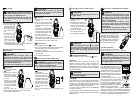
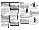
When the meter is on in any
function, the non-contact volt-
age detector will indicate with a
Red LED on the display when
an electric fi eld exceeding 90V
is detected. Place the edge of
the jaw labeled “Voltage Detec-
tor” near the electric fi eld.
Over-fl ow indication
Any time the input exceeds the
measuring range “OL” or “-OL” is displayed.
CAUTION
Clamp the jaws around the conductor under
test and press the MIN/MAX button after an
appropriate range is selected by Auto-rang-
ing function. ZERO and Hz keys are disabled
while MIN/MAX Function is active.
MIN/MAX Function
The MIN/MAX function can be
used during measurements of AC
or DC current, AC or DC voltage,
Temperature (2236-20 only), uA DC
(2236-20 only), and Resistance.
The MIN/MAX function does not
work in the Capacitance or Continu-
ity measurements.
To measure the minimum or maxi-
mum of the function, set the dial to
the appropriate dial position and
then press the MIN/MAX button
to capture the maximum reading.
Press the MIN/MAX button again to
capture the minimum reading.
Press the MIN/MAX button to toggle between
minimum or maximum. The minimum or maximum
reading is displayed and held until the MIN/MAX is
turned off by holding in the MIN/MAX button for 2
seconds or changing the Rotary Dial position.
Non-Contact Voltage Detection (NCVD)