


31
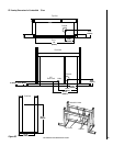
NOTE: DIAGRAMS & ILLUSTRATIONS ARE NOT TO SCALE.
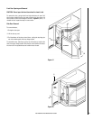
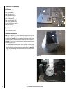
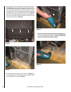
4. Installing the standoffs, parts G. There are 3 standoffs on the top
panel D (see Figure 57). Insert them by taking the lip of the standoff
and sliding them into the slots then push down. Using a sheet metal
screw provided screw them into the hole provided. There is also one
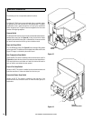
standoff on each the right, left and the back panel. Showing standoff
on left panel C in Figure 58.
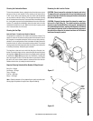
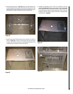
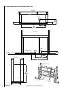
2. Assembling the perimeter - Figure 55
: Using the sheet metal screws
provided, attach the left side panel B and the right side panel C to the
back panel A. There are 3 holes at each corner to connect the panels,
at this point only install the lower two screws at each corner.
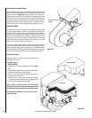
3. Install the top panel D. Place panel D on top of panels A, B, and C as
shown in Figure 56. There are 3 holes across the top of the panel
on each side. Insert the screws only on the right and left side. The 3
remaining holes in panel D will be used in step five.
Figure 55
Figure 56
A
B
C
D
D
E
C
Figure 57
Figure 58