


NOTE: DIAGRAMS & ILLUSTRATIONS NOT TO SCALE.
18
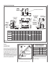
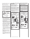
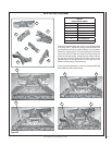
Figure 37
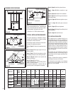
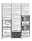
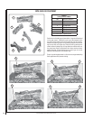
Figure 38
COLD CLIMATE INSULATION
If you live in a cold climate, seal all cracks around
your appliance with noncombustible material
and wherever cold air could enter the room. It
is especially important to insulate outside chase
cavity between studs and under fl oor on which
appliance rests, if fl oor is above ground level.
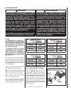
FINISHING REQUIREMENTS
Wall Details
Complete fi nished interior wall. To install
the appliance facing fl ush with the fi nished
wall, position framework to accommodate
the thickness of the fi nished wall (see
Figure 38).
A hearth extension is not required with this
appliance. If a hearth extension is used, do not
block the control compartment access panel.
Any hearth extension used is for appearance
only and does not have to conform to standard
hearth extension installation requirements.
Note: Combustible wall fi nish materials and/or
surround materials must not be allowed to
encroach the area defi ned by the appliance
top spacers. Never allow combustible materi-
als to be positioned in front of or overlapping
the appliance front face and top spacers. See
Figure 38.
Non-combustible materials, such as surrounds
and other appliance trim, may be installed on
the appliance front face with these exceptions:
they must not cover any portion of the glass
or louvers.
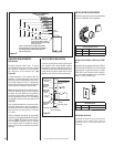
Vertical installation clearances to combustible
mantels vary according to the depth of the mantel.
(refer to Figure 37). Mantels constructed of
non-combustible materials may be installed
at any height above the appliance opening;
however, do not allow anything to hang below
the hood.
Louvers
Louver Face Models
This Area Must Remain
Clear of Combustible
Materials
Top of Appliance
1" Min
(25 mm)
Combustible
Wall Framing
Spacer
Top of Door Frame
Hood must be installed as shown.
Combustible Wall
Framing
Combustible
Finished Wall
Materials
3 in. Min.
(76 mm)
NonCombustible
Finished Wall
Materials
12 (305) MANTEL
10 (254) MANTEL
8 (203) MANTEL
6 (152) MANTEL
4 (102) MANTEL
4
(102)
14
(356)
12
(305)
10
(254)
2 (51) MANTEL
TOP OF
APPLIANCE
6
(152)
NOTE - Hood shown as positioned
in louvered front model. The hood
position in the flush faced front model
is lower than shown.
8
(203)
MANTEL CLEARANCES
Inches (mm)
*Note - The side walls of mantels may protrude
beyond the front face of the fireplace a maximum
of 5 inches (127mm) at 0 inch clearance to the
sides of the fireplace.
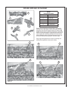
INSTALLATION ACCESSORIES
The following accessory items are available for
use in the installation of this appliance.
White Wall Switch Kit
Cat. No. Model No. Description
85L87 FWSK OFF/ON Wall Switch Kit
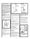
OFF/ON Wall Switch Kit
The OFF/ON wall switch kit may be used to control
the operation of the fi replace burner. Install the
OFF/ON wall switch in a convenient location near
the fi replace.
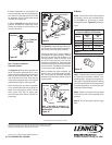
Outside Combustion Air Kits
Cat. No. Model No. Description
81L87 FOAK-4 Combustion Air Kit (w/duct)
81L88 FOAK-4LD Combustion Air Kit (w/o duct)
Outside Air Kits Models FOAK-4 and FOAK-
4LD
Outside Air kits are available with duct (FOAK-4)
and without duct (FOAK-4LD) for use if outside
combustion air is required or desired. If model
FOAK-4LD is used it must be used in conjunc-
tion with locally purchased, non-combustible
Class 1 or Class 0 fl exible duct.
(ref. Form # 750,008M)
(ref. Form # 750,028M & 750,029M)