


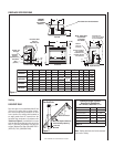
NOTE: DIAGRAMS & ILLUSTRATIONS NOT TO SCALE.
16
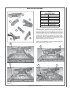
Step 10. CHECKING APPLIANCE OPERA-
TION
With gas line installed run initial system check-
out before closing up the front of the unit. Follow
the pilot lighting instructions provided in the
Homeowner's Care and Operation Instructions.
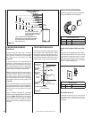
For piezo igniter location see Figure 31
Note: Instructions are also found on the litera-
ture tag attached to the gas valve train.
When fi rst lighting the appliance, it will take
a few minutes for the line to purge itself of
air. Once purging is complete, the pilot and
burner will light and operate as indicated in
the instruction manual. Subsequent lightings
of the appliance will not require such purging.
Inspect the pilot fl ame (remove logs, if neces-
sary, handling carefully).
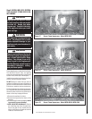
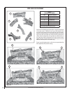
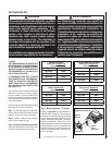
Electronic Appliance Checkout
To light the burner, turn ‘ON’ the optional remote
wall switch and turn the gas control switch to
the “ON” position. Ensure the igniter lights the
pilot. The pilot fl ame should engulf the fl ame
rod as shown in Figure 33.
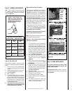
SIT Millivolt Appliance Checkout
The pilot fl ame should be steady, not lifting
or fl oating. Flame should be blue in color with
traces of orange at the outer edge.
The top 3/8" (10 mm) at the pilot generator
(thermopile) and the top 1/8" minimum (tip)
of the quick drop out thermocouple should be
engulfed in the pilot fl ame. The fl ame should
project 1" (25 mm) beyond the hood at all three
ports (Figure 32 ).
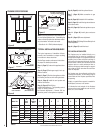
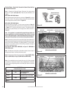
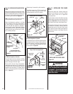
Figure 34
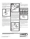
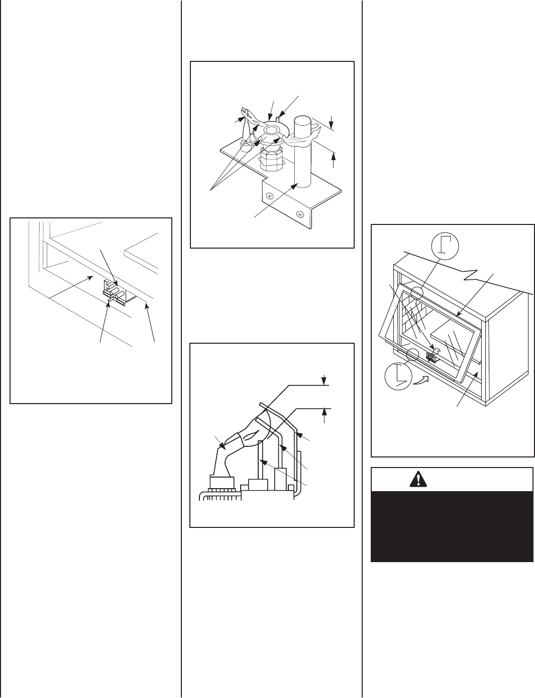
INSTALLING THE GLASS DOOR
Step 11. INSTALLING THE GLASS
DOOR
Retrieve the glass door. Visually inspect the
gasket on the backside of the frame. Gasket
surface must be clean, free of irregularities
and seated fi rmly.
Position the door in front of the fi rebox opening
with the bottom of the door held away from the
fi replace (Figure 34). Hook the top fl ange of the
door frame over the top of the fi rebox frame.
Let the bottom of the door frame swing gently
in towards the fi replace ensuring that the
gasket seats evenly as the door frame draws
shut. Fasten the latch located underneath the
fi rebox fl oor to the door's vee-fl ange. Close the
latch securely.
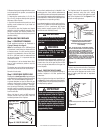
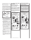
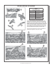
Figure 31
Replace logs if removed for pilot inspection.
To light the burner; turn “ON” the remote wall
switch and rotate the gas valve control knob
counterclockwise to the “ON” position.
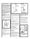
Figure 33
SIT Millivolt Gas Valve
Showing Piezo Igniter Location
Shown with control
compartment door
removed
Piezo Igniter
SIT Millivolt
Gas Valve
Control
Compartment
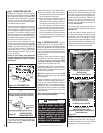
Figure 32
Thermocouple
Thermopile
Pilot
Nozzels
SIT MILLIVOLT PILOT ASSEMBLY
Igniter Rod
Hood
Proper Pilot ance
3/8" to 1/2"
(9 -13 mm)
Ground
Electrode
Flame Rod
Hot Surface
Igniter
Proper Flame
Adjustment
Pilot
Nozzels
ELECTRONIC PILOT ASSEMBLY
Proper Pilot Flame Appearance
Top Flange on
Glass Door
Bottom Vee-fl ange
Glass Door
Glass Door
Firebox Floor
Latch
WARNING
Handle this glass with extreme
care! The glass panel is susceptible
to damage – do not scratch while
handling or while re-installing the
glass door frame.