


13
104468
OWNER’S MANUAL
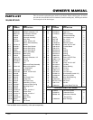
Fan
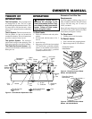
IMPORTANT:
Remove fan from motor
shaft before removing motor from heater.
The weight of the motor resting on the fan
could damage the fan pitch.
1. Remove upper shell (see page 8).
2. Use 1/8" allen wrench to loosen set-
screw which holds fan to motor shaft.
3. Slip fan off motor shaft.
4. Clean fan using a soft cloth moistened
with kerosene or solvent.
5. Dry fan thoroughly.
6. Replace fan on motor shaft. Place fan
hub flush with end of motor shaft (see
Figure 30).
7. Place setscrew on flat of shaft. Tighten
setscrew firmly (40-50 inch-pounds/
4.5-5.6 n-m).
8. Replace fan guard and upper shell.
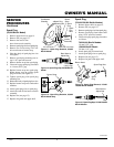
Motor
Shaft
Setscrew
Figure 29 - Fan, Motor Shaft, and Setscrew
Location
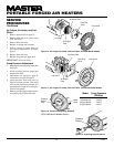
Motor
Shaft
Fan
Setscrew
Figure 30 - Fan Cross Section
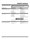
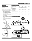
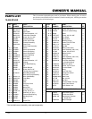
Output Rating (Btu/Hr) 35,000 70,000 100,000 150,000
Fuel Use Only Kerosene or No. 1 Fuel Oil
Fuel Tank Capacity
(U.S. Gal./Liters) 3.0/11.4 5.0/18.9 9.0/34 13.5/51.1
Fuel Consumption
(Gal. Per Hr./Liters Per Hr.) .26/1.0 .49/1.85 .70/2.7 1.1/4.1
Electric Requirements 230 V/50 Hz (Same All Models)
Amperage (Normal Run) .8 1.0 1.2 1.2
Hot Air Output (CFM/CMM) 140/4 225/6.4 425/12 500/14.2
RPM 1425 2850 2850 2850
SPECIFICATIONS
Fan
Flush
SERVICE
PROCEDURES
Continued
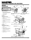
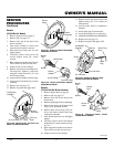
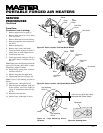
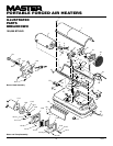
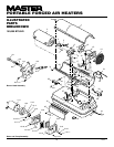
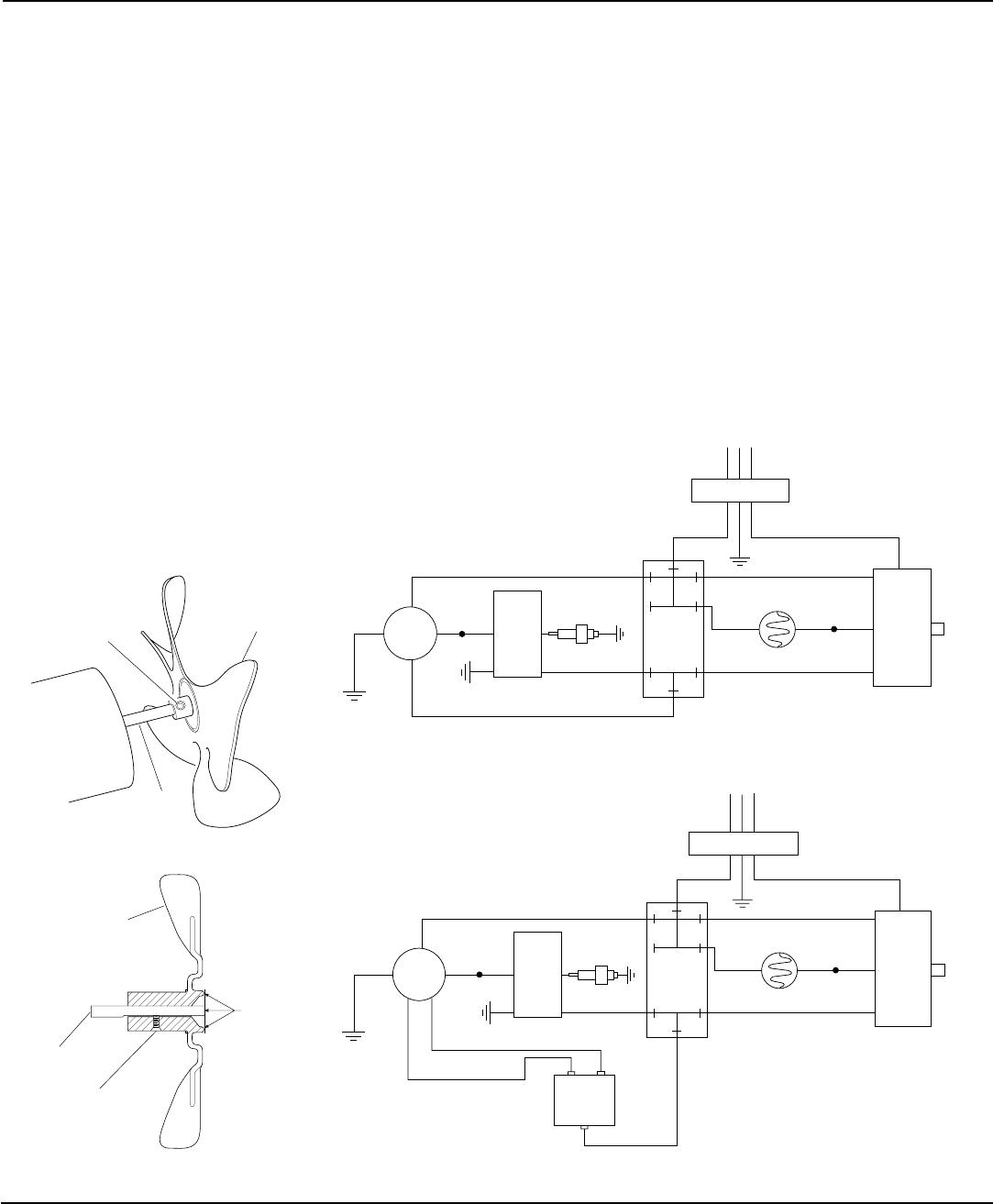
WIRING DIAGRAMS
Ignitor
White
Black
Blue
Green/Yellow
Photocell
Spark Plug
Flame-
Out
Control
B
Reset
Button
R
Red
Blue
White
Black
BrownBlue
White
Red
Red
Orange
Terminal
Board
Motor
Green/
Yellow
Red
Motor
Start
Relay
Black
S or 2 M or 5
L or 1
230V/50Hz
RFI Filter
Figure 32 - Wiring Diagram, 70,000 Btu/Hr Model
Ignitor
White
Black
Blue
Green/Yellow
Photocell
Spark Plug
Flame-
Out
Control
B
Reset
Button
R
Red
Blue
White
Black
BrownBlue
White
Red
Red
Orange Terminal
Board
Motor
Green/
Yellow
230V/50Hz
RFI Filter
Figure 31 - Wiring Diagram, 35/100/150,000 Btu/Hr Models