22 61D0008
7
9
/16"
7
1
/4"
22
1
/16"
15"
30°
A
A
3' min.
Flue Outlet
Height
Flue Outlet
Height
Flue Outlet
Height
3' min.
2' min. when
Dim. “A” is 10'
or Less
2' min. when
Dim. “A” is 10'
or Less
A
CHIIMNEY INSTALLATION
OFFSET INSTALLATION SEQUENCE
(CONTINUED)
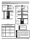
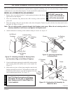
1. Install the first SE30 elbow by placing the extended flue into the mating
part of the fireplace or chimney section. Push down until the outside of
inlet air duct of the elbow overlaps. Snap lock the elbow into the fireplace
or chimney section.
2. Nail the support straps to the framing member with a minimum of two (2)
8-penny nails per strap.
3. Install the sections of pipe between elbows until the proper number of
chimney sections have been installed.
4. Install the second elbow to return the run of the chimney to vertical.
5. Nail the support straps of the second elbow to a building frame member.
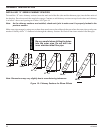
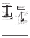
6. Continue installing the vertical portion of the chimney. See Figures 22
and 23.
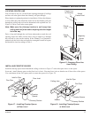
Chimney
Center Line
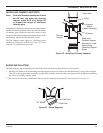
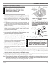
Figure 23 - SF30 Firestop
Spacer
Note: If the inclined portion of the chimney passes through a floor or ceiling, an SF30 firestop spacer should
be installed to provide the firestop and support required. Be sure proper spacing in maintained
between the chimney and combustibles. See Figure 23.
CHIMNEY CAP INSTALLATION
MODEL SC CHIMNEY CAP
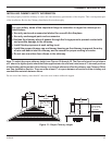
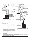
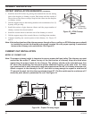
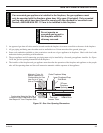
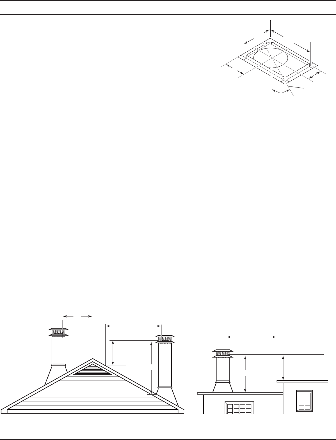
Note: The proper chimney height is important to assure proper draft and safety.The chimney cap must
extend the flue outlet 4" above the top of the last section of chimney. Keep this mind when
determining the proper height for the chimney. The chimney should not be extended more than
90" above the supporting roof structure without additional support. In the case of an “A” frame
type construction or other steep pitch roofs that require more than 90" of chimney above the roof,
attach a support to the chimney at the 90" level that is strong enough to support a wind load of
3
1
/8 pounds for each inch the chimney extends above 90". The flue outlet must be a minimum of 3'
above the point where in penetrates the roof. See Figure 24.
Figure 24 - Proper Chimney Height


