


5 © MARMITEK
Walk Test Mode
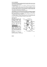
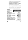
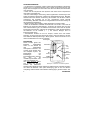
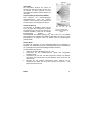
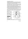
A walk test is performed in order to determine the lens coverage pattern of the
detector – see Figure B.2. Walk Test mode cancels the delay time between
detections, enabling you to perform an efficient walk test.
To perform a Walk Test.
1. Place the Mode jumper over pins 1 & 2.
2. Walk across the scope of the detector according to the detection pattern
selected.
3. Confirm that the LED activates and deactivates accordingly. Wait five
seconds after each detection before continuing the test.
4. After completing the walk test, remove the jumper and place it over one
pin for storage – see Mode Jumper Safeguard.
LED Indication
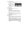
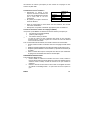
The LED indicator is lit twice every time a transmission is made. To enable or
disable LED indication, refer to Table
B.4 below.
Table B.4: LED Indication Settings
The LED should only be disabled after successfully walk testing the
detector.
Mode Jumper Safeguard
During normal operation, the Mode jumper should be placed over one pin for
storage. When the mode jumper is placed over two pins, the detector is either in
Radio or Walk Test Mode. As a precaution, these modes are limited to three
minutes. After three minutes have expired, the detector switches back to normal
operation. If this happens, you can reset a mode by removing and replacing the
mode jumper.
TECHNICAL DATA
Antenna: Built-in Whip
Frequency: 868.35MHz FM
Power: 3.6V ½ AA Lithium Battery
Current Consumption: 30mA (transmission),
12µA (standby)
Pyroelectric Sensor: Dual Element
Maximum Coverage: 12 x 12m
Pulse Count: 1, 2, 3 or Adaptive
LED Indicator: Selectable
Adaptive Temperature Compensation
RFI Immunity: 30V/m
Operating Temperature: -10 to 60°C
Fire Protection: ABS Plastic Housing
Dimensions: 110 x 60 x 45mm
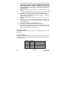
LED Indication MS845
Disabed DIP-Switch 1 OFF
Enabled DIP-Switch 1 ON