


MS845 4
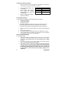
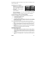
Switch 2 Switch 3 Pulse Count
OFF OFF 1
ON OFF 2
ON ON 3
OFF ON Adaptive
Table B.3: Pulse Count Setting (/MS845)
4. Place the Mode jumper over pins 2 & 3 (Radio Mode); the LED flashes.
Install the Mode jumper only after applying battery power.
5. From the Programming menu, select Devices, Zones [911].
6. Select the zone to which you want to register the transmitter; the system
initiates Registration mode. When Save? appears on the panel’s LCD
display, press 9.
7. Remove the Mode jumper and place it over one pin for storage.
8. Choose an appropriate mounting height from Table B.1 and test the
transmitter from the exact mounting position before permanently
mounting the unit.
9. Knock out the mounting holes and attach the base to the wall.
10. Mount the PCB at the required vertical adjustment and replace the PCB
screw.
11. Write the number of the zone on the sticker provided. Affix the sticker
inside the front cover for future reference and replace the front cover.
Warm-Up Time
The detector will need to warm
up for the first 90 seconds after
applying power.
Pulse Counter
The pulse counter determines
the amount of beams that need
to be crossed before the
detector will generate an alarm. To set the pulse
counter, refer to table B.3.
Adaptive Pulse Count
Using the Adaptive pulse count feature, the
detector chooses between 1 or 2 pulses based on
its analysis of the received signal.
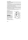
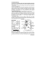
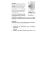
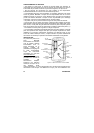
Vertical Adjustment
To position the PCB, turn the Easy Lock counter-
clockwise and slide the PCB up or down to the
required setting using the vertical adjustment
scale. The detector’s coverage area is 12m x 12m
when the PCB is positioned at 0. Slide the PCB up
towards the -8 position to decrease the coverage
area bringing the beams closer to the mounting
wall.
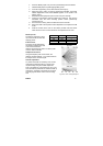
Figure B.2: Lens Coverage Diagrams