


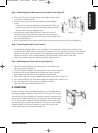
3. INSTALLATION
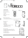
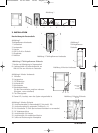
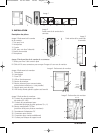
Description of the parts
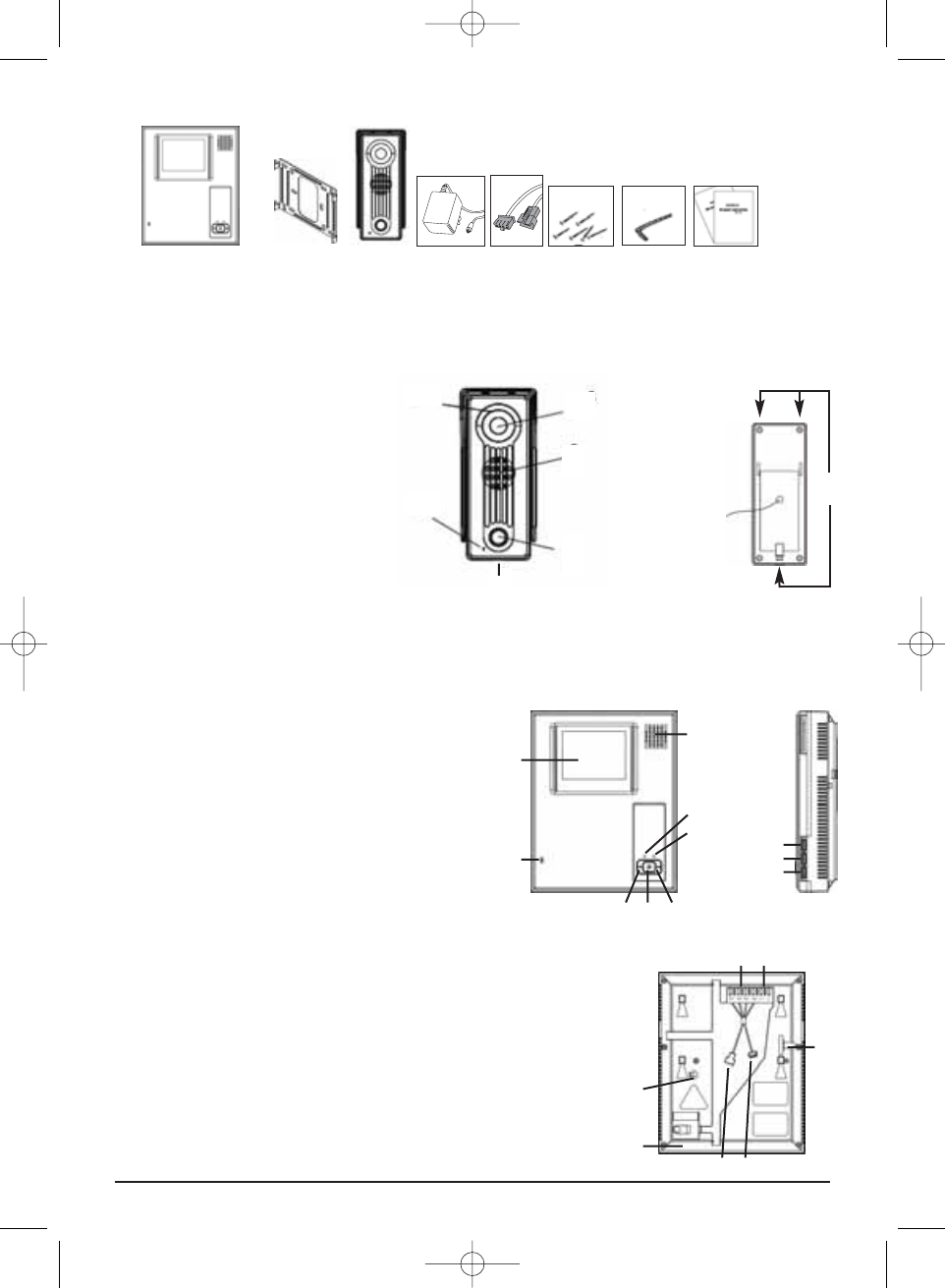
Figure 2. Doorbell camera front
1. Screw hole
2. Loudspeaker
3. Camera
4. LEDs, for visibility in the dark
5. Bell button
6. Microphone
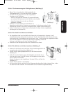
Figure 3. Doorbell camera back
7. Lugs for the attachment of rain cover
8. 4-wire earthed power cable with connector for transfer of image and sound to monitor
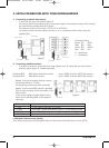
Figure 4. Monitor front
9. Microphone
10. Loudspeaker
11. CRT screen
12. Power ‘On’ LED
13. Monitor button
14. Intercom button (for communication between
multiple monitors, if applicable)
15. Door-open button
16. Power LED, lit when system is On
Figure 5. Monitor back
18. Connection contacts for camera cable (R1 thru R4)
19. Connection contacts for optional door opener (L+, L-)
20. On/Off switch 75 Ohm (for use with multiple monitors)
21. DC adapter connection
22. Connector for camera
23. Connector for extra monitor
24. Slot to block wall plate
4 © MARMITEK
Figure 1.
13
14
15
10
9
11
16
12
4
6
1
5
2
3
1 2 3 4 5 6 7 8
Figure 2.
Doorbell camera front
Figure 3.
Doorbell camera back
volume
brightness
contrast
Figure 4. Monitor front
21
22 23
20
2424
18
19
Figure 5. Monitor back
8
7
DoorGuard300 03-07-2007 12:05 Pagina 4