


MAINTENANCE AND REPAIR
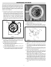
3. Removal of fan blade does not require that the motor wiring be
disturbed. To clean, service or change the fan blade proceed as
follows:
A. Remove the four carriage bolts holding the motor base in
place on the cabinet platform. Mark the platform to reposi-
tion at same location.
B. Loosen the four screws on the cabinet back holding the fan
guard in place.
C. Pull the motor to the rear extending the conduit connection
at the electrical enclosure. Fan blade and hub set screws can
now be accessed by tilting the guard rearward at top or bot-
tom back over the motor shell.
IV. ELECTRICAL COMPONENT SERVICING
EXPLOSION/ELECTRIC SHOCK HAZARD. Disconnect
all power before opening enclosure covers or ser-
vicing heater. Failure to comply could result in per-
sonal injury or property damage.
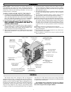
When provided, the following components are located in the cast
aluminum hazardous location enclosure. Remove cover and retain-
ing bolts to gain access the following items (See Figure 16):
1. CONTROL TRANSFORMER
This item is located in the electrical enclosure. It may be
replaced while in the enclosure. To service or replace remove
the quick connect wires and mark their locations. Remove two
screws which hold the transformer in place. Note transformer
orientation and voltage labels on top. Replace transformer in
the same orientation and connect wires. Replace the cast alu-
minum cover and bolt down.
2. CONTACTOR
This component can be removed from the base plate while in
the enclosure. Follow the same steps as indicated for the trans-
former replacement.
3. ALARM PILOT LAMP (OPTIONAL)
To replace the bulb, unscrew the red lens bezel while holding
the lock ring until disengaged. Avoid turning the entire assem-
bly which is held tight to the enclosure with a locking nut on
the inside of the enclosure. It must be re-tightened if loosened
before reuse. Replace the lamp with a 656 type bulb at the cor-
rect control voltage for the unit (120V or 24). Secure the lens
cap (5 threads minimum) against the locking ring and tighten
securely before re-energizing unit. Lamp should flash on
momentarily when unit is energized. See renewal parts section
for part number of replacement bulbs.
9
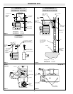
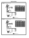
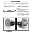
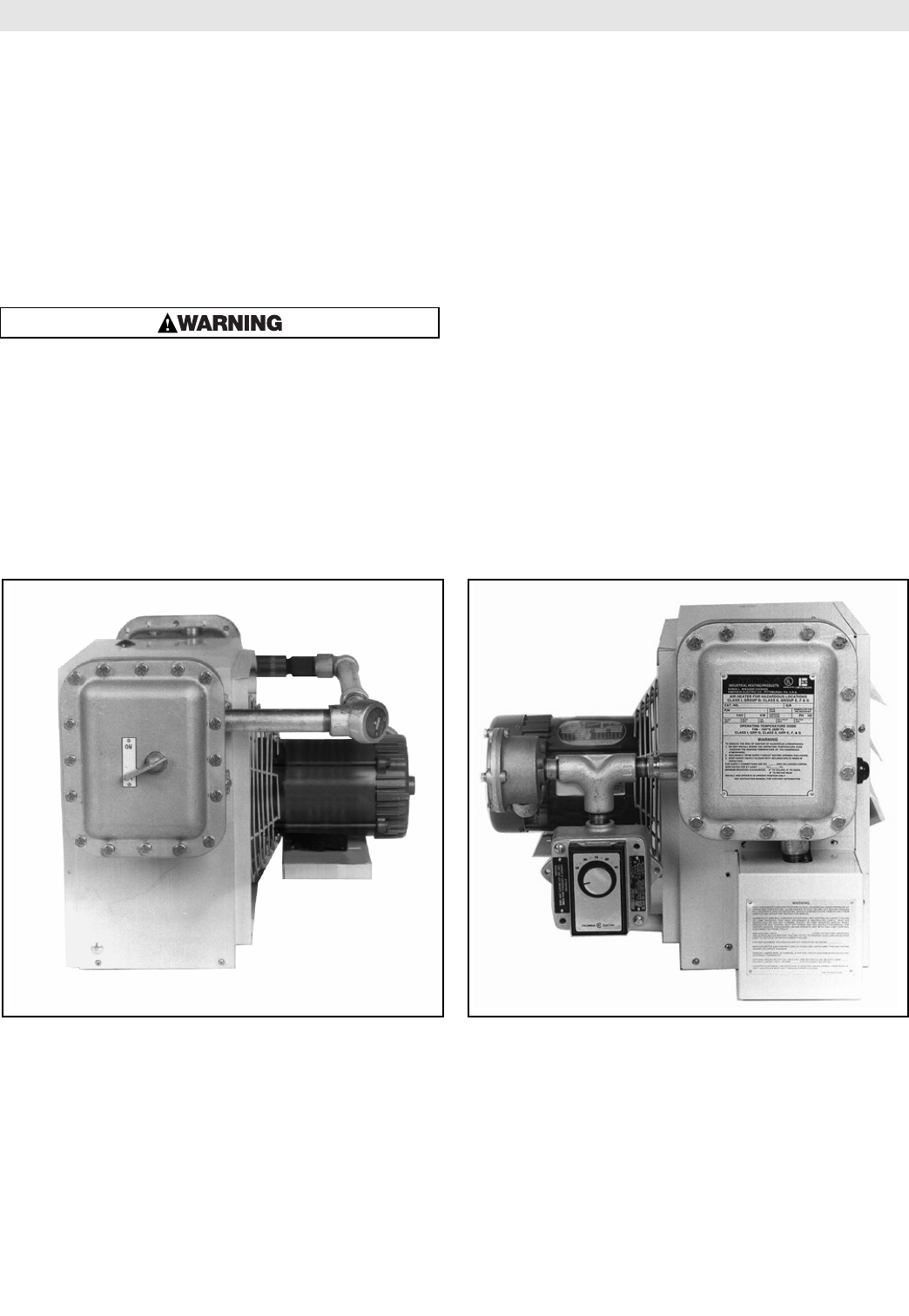
Figure 14
X-Series with Built in Disconnect Switch
(Must use XCMOB Ceiling Mounting Kit)
Figure 15
X-Series with Built in Thermostat