


7
OPERATION
Explosion Hazard. Heater should not be operated in
ambient temperature higher than 40°C (104°F) or
in atmospheres corrosive to the heater itself.
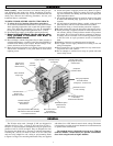
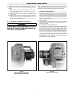
1. The X-Series unit heaters use a sealed water-glycol filled heat
exchanger. The electric immersion elements transfer heat ener-
gy directly to the fluid generating a fluid/vapor mixture which
releases its heat energy to the finned radiator as it rises and
recondenses back to the bottom reservoir to be reheated. This
cycle will continue as long as fan forced air is available on the
finned structure to remove the heat to the airstream.
2. The finned structure of the heat exchanger must be kept clean
and free of accumulated dust and dirt. The cabinet front panel
is easily removed providing access to the heater core for peri-
odic cleaning.
3. Unit should not be operated with louvers fully closed.
Mechanical stops are incorporated into the design of the cabi-
net to limit the degree of closure. Do not force the louvers
beyond these stops.
4. If specified, units are supplied with a built in alarm pilot lamp
which will energize if the manual reset control has a been acti-
vated. During unit startup, the lamp will flash on momentarily
to verify its operation.
MAINTENANCE AND REPAIR
Explosion/Electric Shock Hazard. Disconnect all
power before opening enclosure covers or servic-
ing heaters. Failure to comply could result in per-
sonal injury or property damage.
1. Periodically inspect all electrical connections and terminals to
avoid electrical wiring difficulties. Inspect all wiring for frayed
or worn insulation.
2. Periodically and before each heating season, clean the finned
heat exchanger and fan inlet with compresses air, vacuum, or
water jet. Be sure all electrical covers are tightly closed.
3. If heat output seems to be low, check amperage draw on each
element. Compare measured values to the correct currents as
listed on the unit nameplate.
4. The thermally protected fan motor is permanently lubricated
and sealed. No field servicing is required or should be attempt-
ed. Replace only with a factory supplied identical motor.
Failure to do so will void the factory warranty and may expose
the user to risk of ignition of hazardous atmospheres.
5. Check fan blade to be sure that set screws are tight and there
are no cracks or looseness in the blades. Use factory supplied
replacement blade only.
6. Check for any sign of leaking from the heat exchanger. Too lit-
tle fluid will cause the manual high limit to trip.
7. The sealed heat exchanger contains a glycol/water solution of
propylene glycol. Ethylene glycol is supplied for arctic duty
conditions only. Avoid contact with skin and eyes. If ingestion
should occur, seek medical attention immediately. In case of
eyes or skin contact, wash affected areas with large amounts of
water. The MSDS (Material Safety Data Sheet) for these
materials is available upon request.
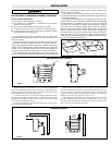
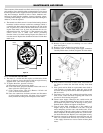
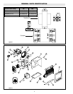
I. REPLACING THE HEAT EXCHANGER
Burn Hazard. Be sure heat exchanger and fluid has
been allowed to cool to 110°F before proceeding.
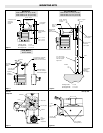
1. Detach the cabinet front by removing screws from all sides of
unit and pulling cover forward off cabinet shell. Detach bottom
panel by removing two screws on each side and two screws in
the rear. Remove the electrical control enclosure lid.
Disconnect the heater and high limit wires from the electrical
control enclosure. Loosen electrical conduit union located
between the heater housing and the electrical control enclosure.
Support the lower end of the heat exchanger and loosen the
three hex head bolts which hold it to the sheet metal. Lower the
heat exchanger away from the sheet metal. Reverse the above
procedure when installing a new heat exchanger.
II. RESETTING MANUAL RESET LIMIT CONTROL
Explosion Hazard. Be sure that all enclosure covers
are replaced and tightly closed before re-energiz-
ing unit after servicing electrical components. High
limit controls must never be bypassed in control
circuit. The factory must perform the replacement
of the immersion heater or overtemperature
cutout. The heat exchanger seal must not be bro-
ken. Consult factory for service.
Maintenance and repair must be performed by qualified personnel only.
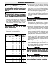
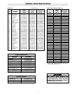
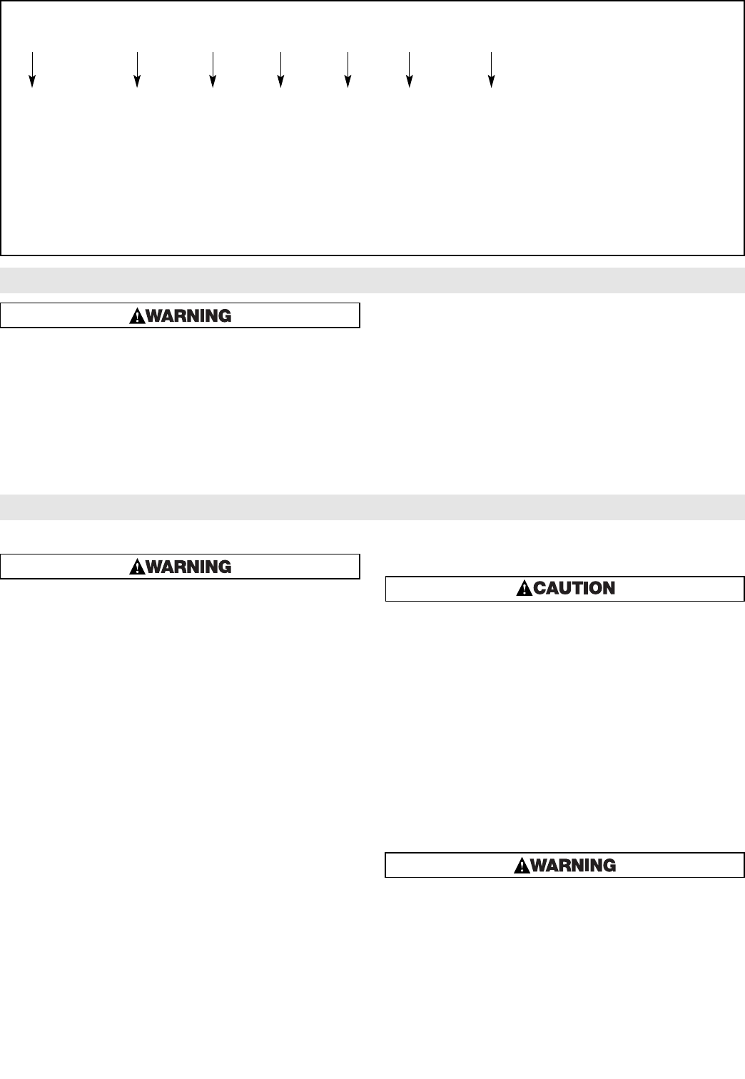
MODEL NUMBER DESCRIPTION
X 300 8 1 2 B T
Series Wattage Voltage Phase Control Version Suffix
Explosion Proof 300=3.0kW 8=208Volt 1=1 Phase 2=24Volt T=Thermostat
Heater for 500=5.0kW 4=240Volt 3=3 Phase 1*120Volt L=Pilot Light (Heater On)
Hazardous 750=7.5kW 48=480Volt K=Pilot Light (Heater Tripped)
Locations 1000=10.5kW 6=575Volt S=Selector Switch (Fan Only)
1500=15.0kW D=Disconnect Switch (15 Amp 3PH)
1800=18.0kW D=Disconnect Switch (30 Amp 1PH)
2000=20.0kW D=Disconnect Switch (30 Amp 3PH)
2500=25.0kW D=Disconnect Switch (60 Amp)
3000=30.0kW
3500=35.0kW
!