


DO NOT ATTEMPT
to assemble blades until you have read thoroughly and understand completely all instructions. To
reduce the risk of personal injury, do not bend the blade brackets when installing the brackets,
balancing the blades, or cleaning the fan. Do not insert foreign objects in between rotating fan blades.
— 5 —
BLADE ASSEMBLY INSTRUCTIONS
1. Open the motor assembly carton and remove the blades carefully, being sure not to scratch the factory finish. If the blades are
preassembled, proceed to the next section; if not, proceed as follows:
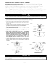
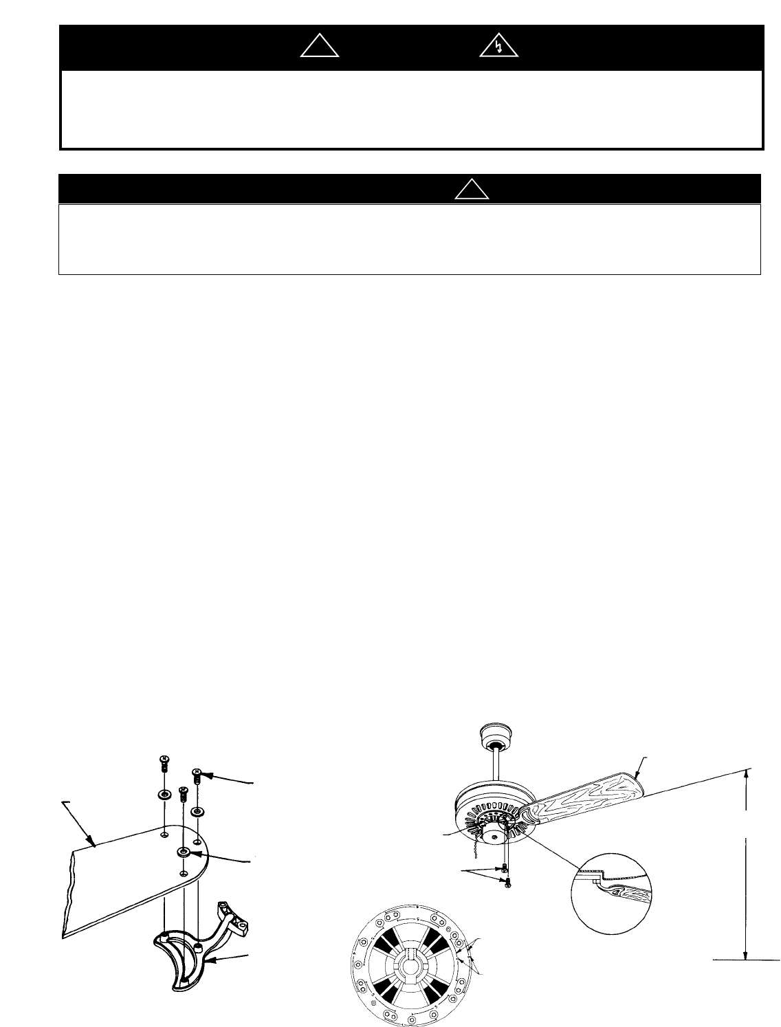
2. In the carton, locate the hardware bag and blade arms. (See Fig. 8)
3. Remove the truss-headed machine screws and washers from the hardware bag. Some assemblies may not require washers.
4. Insert screws (10-24 x 3/8”) through the washers, blade and into the threaded emboss on the blade arm. Assemble, but
do not tighten.
5. After all screws are in place in the blade assembly, alternately tighten each screw evenly until the assembly is secure.
6. Check assembled blade for looseness between the blade arm and blade. If present, continue tightening alternate screws until
secure.
7. Repeat the above procedure for the remaining blades and hardware.
8. Once the blade assembly is complete, proceed with installation.
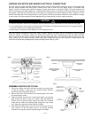
ATTACHING FAN BLADES TO MOTOR HUB (See Fig. 10)
This unit is designed with the capability of being a four or five bladed fan depending on the customer’s preference.
Once the number of blades to be installed has been decided on, perform the following steps carefully to
minimize fan wobble and insure proper fan balance.
1. Please find embossed onto the motor hub the numbers 4, 5 and their guide lines. The 4 and 5 represent the number of
blades to be installed and the guide lines locate the specific screw holes to be used for that blade combination. On
some models this may be in the form of square holes (used for four blade installations) and round holes (used for five
blade installations). (See Fig. 9)
2. First remove and discard the transport bumpers and screws. Position the arm of the assembled blade on the
bottom of the hub. Using the guide lines align the two tapped holes in the hub with the two holes in the blade arm.
Insert the two 10-32 truss head screws into these holes. Tighten the screws down and then back them off slightly
(Approx. 1
1
⁄2 turns).
PETAL
FIG. 8
FIG. 9
BLADE ARM
MOTOR
HUB
“10-32 X 1/2”
LONG SCREWS
BLADE ARM
BENEATH
MOTOR HUB
MOUNTING
SCREW
GUIDE LINES
BLADE
QUANTITY
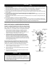
7 FT. MINIMUM
HEIGHT FROM
FLOOR LEVEL
FLOOR LEVEL
FAN BLADE
FIG. 10
SCREWS
WASHER
WARNING
!
ALTHOUGH THE BLADE ARMS ARE INSPECTED AT OUR FACTORY, CARE MUST BE TAKEN IN THE
ASSEMBLY OF THE BLADES SO AS NOT TO DEFORM OR ALTER THE BLADE ARM.
BE CAREFUL NOT TO SLIDE OR SCRAPE METALLIC PARTS ON BLADE’S SURFACE.
a
CAUTION
!