


— 4 —
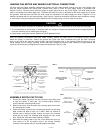
HANGING FAN MOTOR AND MAKING ELECTRICAL CONNECTIONS
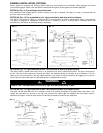
Lift motor with ball hanger assembly attached and position into ball hanger bracket, making sure slot in ball hanger locks
onto ball hanger bracket’s ball locking stud. Connect motor leads to 120V, 60 cycle supply wiring in accordance with
FIgures 5 and 13. Connect ground wire from supply to green ground wire on top of ball hanger. The white lead from the
motor is connected to the white supply wire. The black lead from the motor is connected to the black supply wire to permit
fan operation. Both the black and blue fan motor leads are connected to the black supply wire when a light kit is to be
installed, permitting both fan and light operation. (See Figure 5.) Note that connections should be made outside the canopy.
In some cases, it may be necessary to splice additional wire to existing wiring in order to make connections.
Once the electrical connections have been made, carefully position the leads with the connections pointed upwards
inside the canopy or outlet box. Position the ground wire (green and bare connected wires) and the white connected
wires on one side of the outlet box and/or canopy; the black connected wires on the opposite. Slide the canopy up to the
ceiling making sure the canopy mounting screw heads pass through the key-way slots. Rotate the canopy towards the
narrow end of the key-way and tighten the canopy mounting screws. See Fig. 5 & 6.
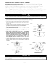
ASSEMBLE SWITCH CUP TO FAN
1. Connect the switch cup plug to the fans connector plug, taking care
to align the guides in each part. This ensures proper electrical
circuit connection (matching lead colors).
2. Remove one screw from the switch cup mounting plate, and loosen
the remaining two screws.
3. Position the switch cup onto fan’s remaining two switch cup mounting
plate screws and twist to latch cup in place. With cup latched at
extreme ends of latching cutouts, replace and secure the removed
screw into the switch cup mounting plate through the cup’s screw
hole. Tighten the other two screws loosened in Step 2.
4. Reconnect the supply power to the fan circuit. Make sure fan’s pull
chain switch is in the off position (hub is not turning) following
connection of the power and prior to performing the next steps.
120V. 60HZ. SUPPLY
BLUE
BLACK CONNECTED
WIRES
CANOPY MOUNTING
SCREWS
DOWNROD MOUNTING HUB
SET SCREWS
CEILING MATERIAL
BALL HANGER DOWNROD
WHITE CONNECTED WIRES
OUTLET BOX APPROVED
FOR FAN SUPPORT
GREEN & BARE FIELD
WIRE (GND.) CONNECTION
BALL HANGER SET
SCREW
CANOPY IN DOWN
POSITION
MOTOR HOUSING
TOP COVER
SWITCH CUP
MOUNTING PLATE
SWITCH CUP
SECURING SCREWS
FAN
SWITCH CUP
CONNECTOR
PLUGS
FAN PULL CHAIN
SWITCH
BALL HANGER
BALL HANGER BRACKET
FIG. 5 FIG. 6
FIG. 7
CEILING
CHECK DOWNROD
MOUNTING HUB SET
SCREWS
FLUSH WITH
CEILING
CANOPY MOUNTING
SCREWS
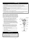
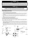
1. Electrical connections should be in accordance with the National Electrical Code and/or all local codes that may apply.
2. To avoid possibility of serious injury or electrical shock, the installer must disconnect the electrical circuit supplying power
to the fan outlet box prior to installing the ceiling fan.
3. Damp location ceiling fans must be installed in a GFCI protected circuit.
a
CAUTION
!