


6
LDVR Series Direct Vent Gas Fireplace
10007317
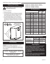
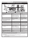
Max. Min.
Input Input
Model Fuel Gas Control BTU/h BTU/h
33LDVRRN Nat Millivolt 16,000 11,200
33LDVRRP Prop Millivolt 16,000 12,000
33LDVREN Nat 24V Hi/Lo 16,000 11,200
33LDVREP Prop* 24V Hi/Lo 16,000 12,000
36LDVRRN Nat Millivolt 19,500 13,650
36LDVRRP Prop Millivolt 19,500 14,625
36LDVREN Nat 24V Hi/Lo 19,500 13,650
36LDVREP Prop* 24V Hi/Lo 19,500 14,625
39LDVRRN Nat Millivolt 23,000 16,100
39LDVRRP Prop* Millivolt 22,500 16,875
39LDVREN Nat 24V Hi/Lo 23,000 16,100
39LDVREP Prop* 24V Hi/Lo 22,500 16,875
43LDVRRN Nat Millivolt 26,000 18,200
43LDVRRP Prop* Millivolt 24,000 18,000
43LDVREN Nat 24V Hi/Lo 26,000 18,200
43LDVREP Prop* 24V Hi/Lo 24,000 18,000
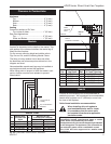
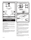
Noncombustible materials such as brick or tile may be
extended over the edges of the face of the fireplace.
DO NOT cover any vent or grille panels.
If a Trim Kit is going to be installed on the fireplace, the
brick or tile will have to be installed flush with the edges
of the fireplace.
Final Finishing
Gas Specifications
33LDVR / 36LDVR / 39LDVR / 43LDVR
Certified To
ANSI Z21.88b-2003 / CSA 2.33b-2003
Vented Gas Fireplace Heaters
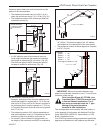
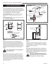
Framing and Finishing
Inlet Minimum 5.5” w.c. 11.0” w.c.
Inlet Maximum 14.0” w.c. 14.0” w.c.
Manifold Pressure 3.5” w.c. 10.0” w.c.
Gas Inlet and Manifold Pressures
Natural LP (Propane)
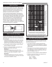
High Elevations
Input ratings are shown in BTU per hour and are
certified without deration for elevations up to
4,500 feet (1,370m) above sea level.
For elevations above 4,500 feet (1,370m) in USA,
installations must be in accordance with the cur-
rent ANSI Z223.1/NFPA 54 and/or local codes hav-
ing jurisdiction.
In Canada, please consult provincial and/or local
authorities having jurisdiction for installations at
elevations above 4,500 feet (1,370m).
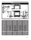
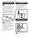
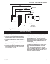
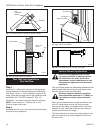
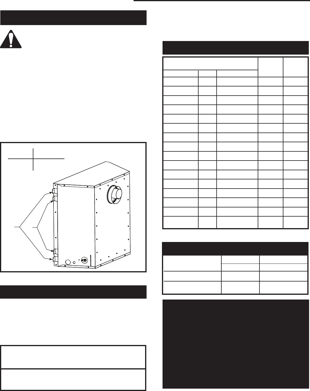
Check fireplace to make sure it is levelled
and properly positioned.
To mount the appliance:
1. Choose the location.
2. This unit comes with four (4) flanges pre-mounted
on both sides of the fireplace to allow two different
drywall thicknesses to be used. Flange “A” is for
1/2” drywall while flange “B” is for 5/8” drywall.
3. Bend the desired flanges out 90° on both sides of
the fireplace. Slide the fireplace into the framed
opening until the flanges contact the front surfaces
of the framing. Level the unit and secure it firmly in
place.
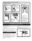
FP1544
nail flange
1/05
Fig. 4 Nailing flanges.
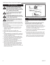
Flange Drywall
Position Depth
A 1/2” / 13 mm
B 5/8” / 16 mm
Flange Location for
Desired Drywall Depth
FP1539
A
B
33LDVR units: GFRN2I0, GFRL2I0, GFRE2I0
36LDVR units: GFRN2J0, GFRL2J0, GFRE2J0
39LDVR units: GFRN2K0, GFRE2K0
43LDVR units: GFRN2N0, GFRE2N0
*Using conversion kit