


Paradox Magellan Systems 7
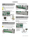
For UL compliant installations, the Magellan console must
be able to seize the telephone line and place a call in an
emergency situation. It must be able to do this even if other
equipment (telephones, answering machines, computer
modems, etc.) already has the line in use. To do so, the
Magellan console must be connected to a properly installed
RJ31X jack that is electronically in series with and ahead of
all other equipment attached to the same telephone line.
Proper installation is depicted in the diagram below. If you
have any questions concerning these instructions, you
should consult your telephone company about installing
the RJ31X jack and the Magellan console for you.
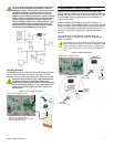
Line Plug Connect
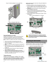
The Magellan console can also be connected to a telephone line
via its on-board
LINE
plug. See Figure 4 on page 7 for more
information on connecting the telephone line using this method.
When connecting via the
LINE
plug, if the telephone line is
shared and it is busy (i.e. someone is talking on the
telephone) the console will be unable to communicate with
the Central Monitoring Station. It is recommended that the
Direct Connect method (page 6) be used to connect the
telephone line.
Figure 4: Line Plug Connection
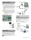
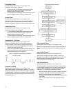
Programmable Outputs (PGMs)
Magellan comes equipped with two 50mA solid-state PGM
outputs. When a specific event occurs in the system, a PGM can
be programmed to activate lights, garage door openers, etc. See
Programmable Outputs on page 30 for more information on
programming PGMs.
Connect Magellan’s PGM outputs as shown in Method 1 in
Figure 5 on page 7. Since Magellan does not come with a power
supply, an external power supply must be employed to power the
circuit. The PGM outputs can be either Normally Open (N.O.) or
Normally Closed (N.C.) as detailed in PGM Normal State on
page 30.
If the current draw on the PGMs is to exceed 50mA, we
recommend using an external relay as shown in Method 2 in
Figure 5 on page 7.
Using Method 2, connect the device to the output terminal of the
external relay that matches the normal state of Magellan’s PGM
output. For example, if PGM1’s normal state is Normally Open
(N.O.), connect the device to the
N
.
O
. terminal of the external
relay.
Figure 5: PGM Connections
4-pin
RJ-11
cable
Back view of the Magellan console.
1
2
1.Insert one end of the 4-pin RJ-11 cable into the
LINE
plug of the Magellan console.
2.Insert the other end of the RJ-11 cable into a
standard telephone wall plug.
External
Power Supply
Devices
such as a
light, etc.
Devices
such as a
light, etc.
External
Power Supply
Method 1
(less than 50mA)
Method 2
(exceeds 50mA)
Back view of the Magellan console.
External
relay