


Attaching Wires
4.Hold the base against the wall, with the wires
coming through wherever it is convenient for wiring.
Route the wires to below the terminal block. Position
the base for best appearance (to hide any marks
from an old thermostat). An optional wall plate is
included for covering old mounting holes. Attach the
base to the wall with the two screws provided.
REMOVING THE OLD THERMOSTAT
Switch electricity to the furnace and air
conditioner OFF; then proceed with the
following steps.
1.Remove cover from old thermostat. Most
are snap-on types and simply pull off.
Some have locking screws on the side.
These must be loosened.
2.Note the letters printed near the terminals.
Attach labels (enclosed) to each wire for
identification. Remove and label wires one
at a time. Make sure the wires do not fall
back inside the wall.
3.Loosen all screws on the old thermostat
and remove it from the wall.
MOUNTING THE UNIT ON THE WALL
1.Strip insulation 3/8 in. (9.5mm) from wire ends and clean off any corrosion.
2.Fill wall opening with non-combustible insulation to prevent drafts from
affecting the thermostat.
3.Press up on the button on bottom of
thermostat and swing the body away
from the base and up to remove the
body from the base.
CAUTION
Read instructions carefully
before removing any wiring
from existing thermostat.
Wires must be labeled before
they are removed. When
removing wires from their
terminals, ignore the color of
the wires since these may not
comply with the standard.
CAUTION
Be careful not to drop the body or disturb electronic parts.
Leave the cover closed while the body is being removed from the base.
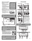
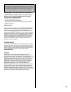
TERMINALS
SCREW
ANCHORS
BASE
W3 L
R
G
O
GYWRHBORC
CAUTION
Do not allow wires to touch each other or parts on
thermostat. Wires must be trapped between black spacer
and brass terminal. Also, be sure to tighten securely all 7
electrical terminal screws.
NOTE
If you are mounting the base to a soft material like plasterboard
or if you are using the old mounting holes, the screws may not
hold. Drill a 3/16-in. (4.8mm) hole at each screw location, and
insert the plastic anchors provided. Then mount the base as
described below.
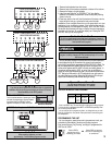
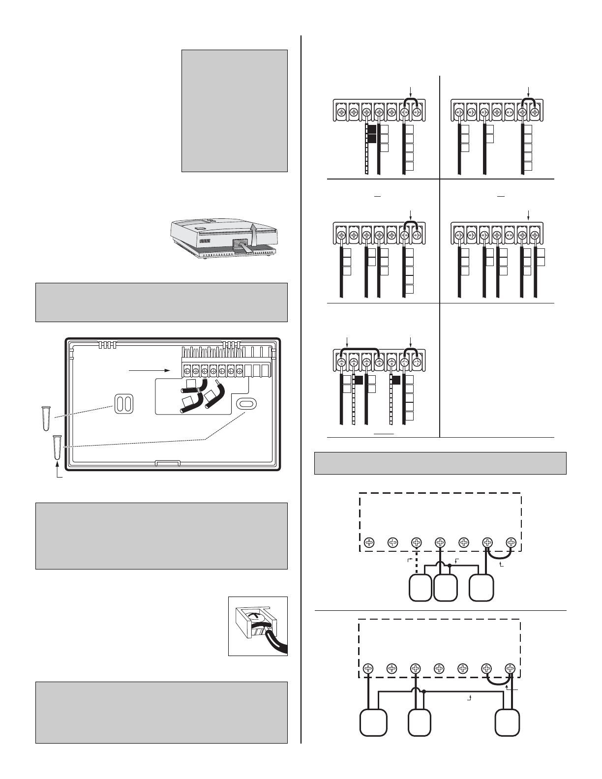
WIRING DIAGRAMS
HEATING ONLY SYSTEMS COOLING ONLY SYSTEMS
4 -WIRES WITH ONE TRANSFORMER 5 -WIRES WITH TWO TRANSFORMERS
HEATING / COOLING SYSTEMS HEATING / COOLING SYSTEMS
YOGWBRHRC
OPTIONAL FAN WIRE
RC-RH JUMPER
PROVIDED
RH
RC
R
V
5
G
F
W
H
4
YOGWBRHRC
RC-RH JUMPER
PROVIDED
RH
RC
G
F
R
V
5
Y
C*
6
YOGWBRHRC
RC-RH JUMPER
PROVIDED
RH
RC
R
V
5
V
5
W
H
4
Y
C*
6
G
F
YOGWBRHRC
RC-RH JUMPER
PROVIDED
*CUSTOMER
SUPPLIED
JUMPER
RH
RC
R
Y
C*
G
F
YOGWBRHRC
RC-RH JUMPER
REMOVED
RH
V
5
TYPICAL SINGLE STAGE
HEAT PUMP WIRING
W
H
4
Y
C*
6
G
F
RC
R
O B
USE B or O NOT BOTH
WIRING DIAGRAM NOTES
(APPLIES TO ALL DRAWINGS)
• The DASHED lines are optional
depending upon your system type.
• Verify whether “C”, “X” or “B” wires
are connected to system common.
• If “B” and “O” are both present, it is
likely that “B” is a system common.
• If a “B” wire in your system is a
common, then connecting it to the
“B” terminal may cause damage to
your system.
• If “Y” and “C” are both present, it is
likely that “C” is a system common.
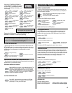
These diagrams below are provided for new installations or
unreferenced wires.
TYPICAL HOOKUP FOR 2 OR 3 WIRE
24 VAC HEATING SYSTEMS (AND MILLIVOLT)
Y O G W B RH RC
Gas
Valve
or
Heater
FAN
System
XFMR
RH-RC JUMPER
PROVIDED
OPTIONAL
FAN LEAD
COMMON
TYPICAL COOL HOOKUP
24 VAC SYSTEMS
Y O G W B RH RC
FAN
A/C
Comp.
System
XFMR
RH-RC JUMPER
PROVIDED
SYSTEM
COMMON
2