


3 Troubleshooting
46
Service Manual
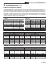
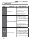
Combustion Analysis Procedure
1. Turn the main power off to the boiler by placing the
“On/Off” switch in the OFF position.
2. Remove the flue temperature sensor from the flue pipe
connection. Note: Combustion measurements will be
made at this point.
3. Turn the main power on to the boiler by placing the
“On/Off” switch in the ON position.
4. Place the boiler into the active position by pressing the
RIGHT SELECT [ON] key (see page 7).
5. Locate the pinhole button below the RESET button on
the display board (see page 7). Insert a thin wire (such
as a paper clip) into the hole and press the button once
and hold for 5 seconds to place the boiler into Service
Mode. In Service Mode the boiler will fire at ignition
speed and will then modulate up to full fire.
6. Insert the probe from a combustion analyzer into the
hole left by the removal of the flue temperature sensor.
7. Once the boiler has modulated up to full fire, measure
the combustion. The values should be in the range
listed in Table 3-5 above. The CO levels should be less
than 150 ppm for a properly installed unit.
If the combustion is not within the specified range,
reference the chart below for possible causes and
corrective actions.
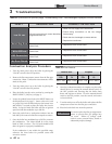
Table 3-5 Flue Products
Natural Gas Propane
CO
2
O
2
CO
2
O
2
8.0% - 10% 3.0% - 6.5% 9.0% - 11% 4.1% - 6.9%
8. Once the combustion analysis is complete, test the safety
shutoff device by turning the manual shutoff switch to
the OFF position and ensuring that the boiler shuts
down and registers an alarm. Turn the manual shutoff
switch to the ON position, reset the control, and return
to Service Mode.
9. Turn the main power off to the boiler and replace the flue
temperature sensor into the flue pipe connection.
10. Place the boiler back into normal operation.
You must replace the flue gas temperature
sensor to prevent flue gas spillage into
the room. Failure to comply could
result in severe personal injury, death, or
substantial property damage.
ƽ WARNING
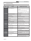
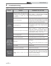
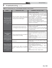
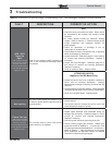
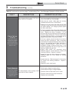
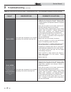
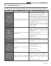
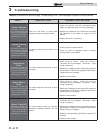
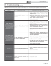
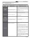
Table 3-4 (continued from previous page) Troubleshooting Chart - Fault Messages Displayed on Boiler Interface
FAULT DESCRIPTION CORRECTIVE ACTION
Low 24 vac
120 vac input to the main control board has
dropped below 80 vac.
• Check 120 vac supply to the transformer.
• Check wiring connections at the low voltage
terminal strip.
• Check the wire size/length to remote devices.
• Replace the transformer.
Watch Dog Error
The main control board has detected an
internal fault.
• Replace the main control board.
Write EEProm
The main control board has detected an
internal fault.
• Replace the main control board.
CRC Parameters
The main control board has detected an
internal fault.
• Replace the main control board.
No Error Stored
The main control board has detected an
internal fault.
• Replace the main control board.