


63
Installation & Operation Manual
11 Operating information
General
How the boiler operates
The Knight wall mount boiler uses an advanced stainless
steel heat exchanger and electronic control module that
allows fully condensing operation. The blower pulls in air
and pushes flue products out of the boiler through the heat
exchanger and flue piping. The control module regulates
blower speed to control the boiler firing rate. The gas valve
senses the amount of air flowing into the boiler and allows
only the right amount of gas to flow.
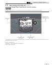
How the control module operates
The SMART SYSTEM control module receives inputs
from boiler sensors and external devices. The control
module activates and controls the blower and gas valve to
regulate heat input and switches the boiler, Domestic Hot
Water (DHW), and system pumps on and off as needed.
The user programs the module to meet system needs by
adjusting control parameters. These parameters set operating
temperatures and boiler operating modes. Boiler operation
can be based on boiler outlet water temperature, boiler inlet
water temperature, system temperature, a 0 - 10V signal, or
Modbus, depending on the parameter settings.
Control inputs and outputs
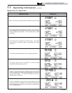
Room thermostat
There are three (3) heat/loop demand connections available
on this control. These inputs tell the boiler to provide
water for space heating. Each thermostat connection has its
own set point and outdoor air reset curve. When multiple
thermostats have a call for heat the control will give priority
to the demand with the highest set point.
Example: Assume that both heat/loop demand
1 and heat/loop demand 2 have a call for heat.
Demand 1 has a set point of 110°F. Demand 2 has a set point
of 140°F. The boiler will regulate the system temperature to
140°F until Demand 2 has been satisfied. Once Demand 2
has been satisified the boiler will provide 110°F water to the
system.
SMART SYSTEM Multi-temp loop control
The Knight wall mount boiler is capable of producing up
to three (3) set point temperatures to meet different space
heating demands. This device controls the temperatures
of up to three (3) separate loops, based on the settings for
the three (3) heat/loop demands (reference Lochinvar kit
RLY30086).
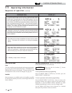
0 - 10V input (set point or power)
The Knight wall mount boiler can be controlled by a Building
Management System (BMS) using a 0 - 10 vdc signal. The
control can be configured by the installer to use this signal to
either control set point or firing rate.
The Knight wall mount boiler can also be programmed to
accept a call for heat from a 0 - 10V signal, reference the Knight
Wall Mount Service Manual for a detailed explanation of this
procedure.
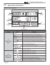
DHW priority
The SMART SYSTEM control allows the connection of a DHW
thermostat or tank sensor to the low voltage connection board.
When a tank sensor is connected, the DHW thermostat input
is ignored. When a boiler is programmed for DHW Normal
Mode, the maximum firing rate can be limited to match the
input rating of the indirect tank coil.
DHW / space heating (SH) cycling
If a DHW call for heat is received while a space heating call is
in progress and the DHW is in Normal Mode, the control will
start the DHW pump and shut the boiler pump off. The system
pump will remain on. For stand-alone boilers, if the space
heating call is still active while the DHW call is in operation, the
control will wait for 30 minutes (time adjustable by installer)
then it will switch back to the space heating demand. There is
a timer to switch from space heating to DHW and a timer to
switch from DHW to space heating. The control will switch
back and forth until one of the heat demands end.
Programmable controlling sensor
The control module is programmed to use the outlet sensor
as the control sensor by default. If a system supply sensor
is connected, the control automatically uses it as the control
sensor. The control sensor can be changed by the installer to
the inlet sensor. If the inlet sensor is chosen as the controlling
sensor, it is recommended that the system supply sensor
be installed in order to provide the best control of the inlet
temperature.
Anti-cycling
After the burner turns off, the control will delay the next burner
cycle for a set time period (time is adjustable by the installer).
The time delay will be bypassed if the inlet water temperature
drops too far during the delay.
Boiler and system pump control
The boiler pump will run whenever the burner is firing, unless
the DHW is programmed for Normal Mode and the boiler is
heating the DHW tank. The boiler pump will run during Freeze
Protection Mode as well. It will continue to run for a short time
after the burner turns off or the Freeze Protection Mode ends.
The system pump will run whenever there is a space heating call
for heat, or the boiler goes into Freeze Protection Mode. It may
be programmed to run during a DHW call for heat when the
DHW is programmed for Zone Mode. It will continue to run
for a short time after the end of the heat demand or the Freeze
Protection Mode. The system pump can be programmed to run
continuously if desired, except during outdoor shutdown and/
or a DHW call for heat.
ƽ CAUTION
When multiple temperature loops are
used, mixing valves are required for the
protection of any low temperature loops.