


NOTE: DIAGRAMS & ILLUSTRATIONS NOT TO SCALE.
6
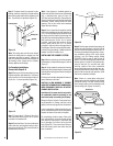
Step 3. Refer to fireplace drawings and specifi-
cations on pages 6 and 7 for framing dimensions
and details. Frame appliance enclosure as illus-
trated in
Figures 12 through 15
on page 7.
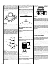
IMPORTANT: UNDER NO CIRCUMSTANCES
CAN THE FIREPLACE TOP SPACERS (
SEE
FIGURE 11
) BE REMOVED OR MODIFIED,
NOR MAY YOU NOTCH THE HEADER TO FIT
AROUND OR BE INSTALLED LOWER THAN
THE SPACERS. THE HEADER MAY BE IN DI-
RECT CONTACT WITH THE TOP SPACERS
BUT MAY NOT BE SUPPORTED BY THEM.
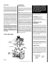
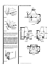
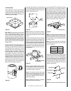
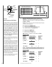
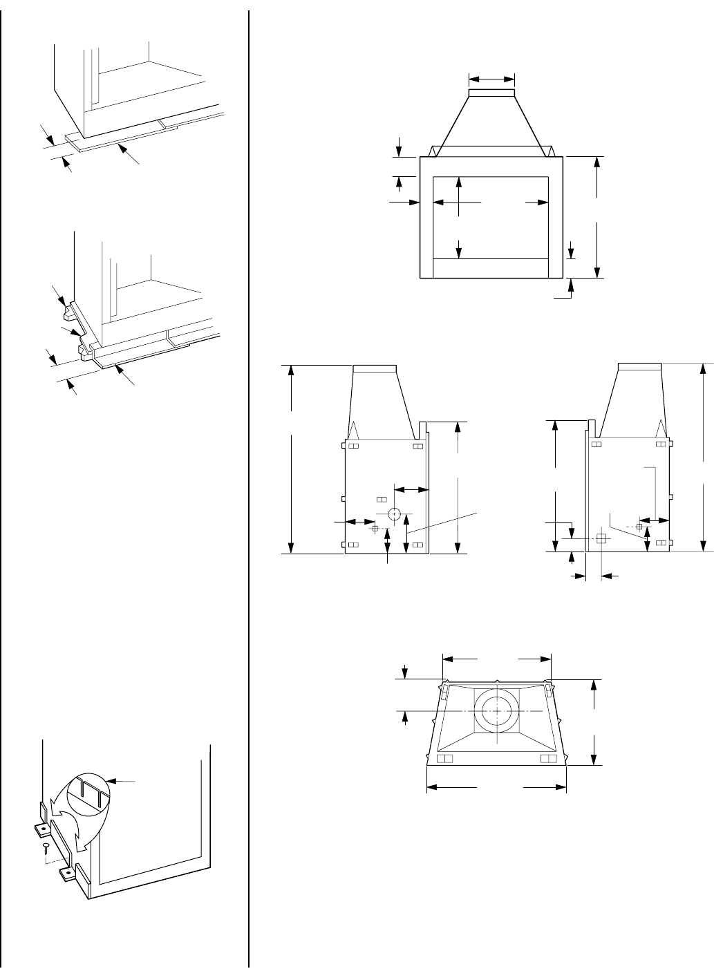
Step 4. Fireplace may be anchored to floor.
Bend down four (4) anchor tabs located at the
base of the fireplace and secure to the floor by
nailing with 8d nails (
Figure 10
).
Note: The “Z” type safety strip is not supplied.
Figure 8
Figure 9
Figure 10
Anchor
Ta b
Metal Safety Strips
with 1" (25mm)
Overlap
2"
(51mm)
Special “Z” Metal
Safety Strips with 1"
(25mm) Overlap
2"
(51mm)
Blocking
Platform
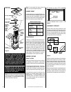
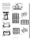
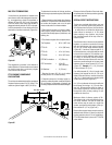
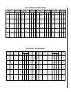
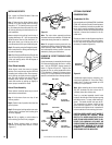
FIREPLACE SPECIFICATIONS
Figure 11
15" O.D.
(381 mm)
6 ⁹⁄₁₆"
(167 mm)
5 ⁵⁄₁₆"
(150 mm)
36"
(914 mm)
29"
(737mm)
42 ⁹⁄₁₆"
(1081 mm)
7"
(178 mm)
66 ¹⁄₁₆"
(1678 mm)
10 ³₄"
(273 mm)
47 ¹⁄₈"
(1197 mm)
10 ⁵⁄₈"
(270 mm)
8 ³⁄₄"
(222 mm)
11"
(279 mm)
66 ¹⁄₁₆"
(1678 mm)
4 ¹⁄₂"
(114 mm)
47 ¹⁄₈"
(1197 mm)
10 ⁵⁄₈"
(270 mm)
8 ³⁄₄"
(222 mm)
4 ¹⁄₈"
(105 mm)
37 ¹⁄₄"
(946 mm)
11"
(279 mm)
29 ⁷⁄₁₆"
(748 mm)
47 ⁷⁄₈"
(1216 mm)
Front View
Top View
Right Side
Left Side