


NOTE: DIAGRAMS & ILLUSTRATIONS NOT TO SCALE.
14
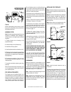
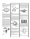
Return
Elbow
Figure 41
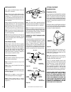
Note: The return elbow assembly performs
the same function as a stabilizer. Consider this
when determining the need for a stabilizer.
Note: Do not apply excessive pressure to any
subsequent chimney section following return
elbow assembly when installing. Ensure that
each subsequent chimney section is securely
attached by testing as noted above.
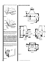
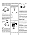
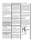
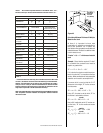
CHIMNEY 30° OFFSET THROUGH FLOOR
OR CEILING
It may be necessary to assemble the chimney at
30° when passing through the floor or ceiling
area. Use the F10FS30-2 firestop spacer as
shown in
Figures 42 and 43
. Support the
chimney at floor or ceiling penetration with a
FTF10 stabilizer if distance of chimney below
ceiling is 10' or more. Maintain 2" minimum air
space to combustibles from chimney sections.
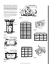
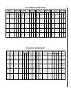
INSTALLING OFFSETS
First, review the Offset Elevation Chart and
Figure 40
for reference.
Step 1. Determine the offset distance where
chimney is to pass through the first ceiling-
dimension “A.” To find this point on your ceil-
ing, first determine the center point for a verti-
cal chimney following the instructions for ver-
tical installation.
Measure height to the ceiling from the top of
fireplace-dimension “B.” Use the appropriate
Offset Elevation Chart to find dimension “A.”
Mark point where you will drive your nail to
show the center point for your offset ceiling cut.
Step 2. Proceed by using the Straight Up Instal-
lation Instructions for cutting and framing ceil-
ing and roof openings.
Note: See Framing and Dimension Chart for the
sizes of the ceiling and roof openings. The size
of the roof opening varies with the degree of
pitch of the roof.
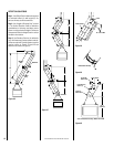
Offset Elbow Assembly
Offset elbows install the same as chimney
sections. First, snap the inner section INTO the
preceding inner section of flue. Check connec-
tion by pulling up slightly to ensure a tight fit.
Next, the outer sections snap lock OVER the
preceding outer section of chimney. Again,
check outer section by pulling up slightly to
ensure proper connection is made.
Return Elbow Assembly
Return elbows install the same way as round
terminations and stabilizers:
Step 1. Hold return elbow over top of last
chimney section.
Step 2. Center inner slip section into inner flue
pipe-slip down.
Step 3. Center outer-locking section over outer
chimney pipe. Push down until locking joint
has firmly engaged.
Step 4. Pull up slightly on return elbow to
ensure locking joint has firmly engaged.
Step 5. Secure support straps to framing
members by nailing under tension in sheer
(
Figure 41
).
F10FS30-2
Firestop Spacer
FTF10-S4
Stabilizer
2" Min.
Air Space
30° Firestop
And Attic Above
10'
Max.
Attic Space
2" Min.
Air Space
F10FS30-2
Firestop Spacer
FTF10-S4
Stabilizer
30° Firestop
And Room Above
10'
Max.
Room Above
2" Min.
Air Space
2" Min.
Air Space
Figure 43
Figure 42
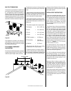
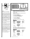
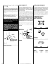
OPTIONAL EQUIPMENT
CONSIDERATIONS
Combustion Air Kits
Use combustion air kit, Model FOAK-4 or Model
FOAK-4LD, with the Colonial Series fireplaces.
Refer to installation instructions packed with
the air kit for specific installation information.
The outside air kit must be installed before the
fireplace is framed and enclosed in the fin-
ished walls.
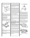
Outside air drawn into the fireplace supplies air
to the fire for combustion. Only one combus-
tion air duct on the left side of the fireplace is
necessary if installed (
Figure 44
).
Figure 44
If additional length of duct is necessary, pur-
chase locally available U.L. Class 0 or Class 1
metallic duct. The duct may extend up to 50'
(15.24 m) in any direction.
Note: When installing the air duct vertically,
DO NOT terminate the duct closer than 3'
(914mm) below the chimney top.
There is a one-hand operated shut-off valve
located in the left side of the fireplace opening
behind the screen. To open, rotate handle up-
wards. The handle should lock open at 45°.
The combustion air damper should be fully
open when the fireplace is in use and fully
closed when the fireplace is not in operation to
prevent outside air from entering your home.
CAUTION: NEVER LOCATE INLET WHERE IT
CAN BE BLOCKED BY SHRUBS, SNOW
DRIFTS, ETC. NEVER LOCATE INLET IN GA-
RAGE OR ANY AREA WHERE THERE IS AN-
OTHER FUEL-BURNING APPLIANCE OR
PRODUCTS EMITTING COMBUSTIBLE GASES
SUCH AS PAINT, GASOLINE, ETC. IN COLD
CLIMATES IT IS RECOMMENDED THE COM-
BUSTION AIR DUCT BE INSULATED.
Provision for
Outside Air