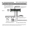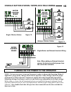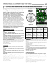
9. See Figure 9 for
connecting the
photoelectric
device to the
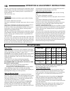
operator. See Page
17 for proper
setting of the
selector switches.
These switches
must be properly set and an approved photoelectric device or
approved door edge device connected to the operator to obtain
B2 Mode of Operation, Momentary Contact to Close.
DOOR EDGE and PHOTOELECTRIC INSTALLATION
13
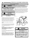
TO AVOID DAMAGE TO DOOR AND
OPERATOR ENSURE ALL DOOR LOCKS ARE
DISABLED.
USE AN INTERLOCK SWITCH IF A LOCK IS
REQUIRED TO RETAIN FUNCTIONALTY.
CAUTION
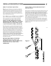
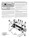
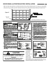
Figure 8
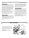
Door Edge
Device
Note: See the door edge manufacturer‟s installation instructions for the complete installation procedure. See Figure 9 for connecting the
edge to the operator. See Page 17 for proper setting of the selector switches. These switches must be properly set and an approved photo-
electric device or approved door edge device connected to the operator to obtain B2 Mode of Operation, Momentary Contact to Close.
Door Edge Installation Illustration


