


12
APPLICATION/INSTALLATION GUIDELINES
Location Guidelines
To ensure an adequate air supply,
locate drycoolers in a clean air
area, away from loose dirt and for-
eign matter that may clog the coil.
In addition, drycoolers must not
be placed near steam, hot air, or
fume exhausts. Also, drycoolers
should be no closer than 3 feet
from a wall, obstruction or adja-
cent unit with no obstructions over
the unit. Install drycoolers in a
level position to assure proper vent
and drain.
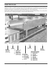
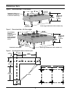
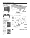
All drycooler legs have mounting
holes for securing the unit to steel
supports or concrete pads.
For roof installation, mount dry-
coolers on steel supports in accor-
dance with local codes. To
minimize sound and vibration
transmission, mount steel sup-
ports across load-bearing walls.
For ground installations, a con-
crete pad will support the load.
Drycooler Installation
The drycooler should be located
for maximum security and main-
tenance accessibility. Avoid
ground level sites with public
access or areas which contribute
to heavy snow or ice accumula-
tions. Utilize centrifugal fan dry-
coolers when placing a drycooler
in a building.
Electrical Requirements of
the Drycooler
Electrical service is required for
all drycoolers at the location of the
outdoor system. The power supply
does not necessarily have to be the
same voltage supply as required
by the indoor unit. This separate
power supply may be 208, 230,
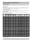
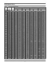
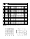
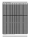
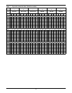
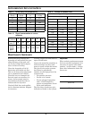
460 or 575 volt, 60 Hz. For electri-
cal characteristics of the standard
voltage drycoolers, see Full Load
Amps (FLA) of the drycooler in
Tables 6 and 7 and FLA of the
pump, if used, in Table 8. Dual
element, time delay type fuses or
“HACR” circuit breakers at the
main power source. The only elec-
trical connection between the
indoor unit and the drycooler is a
two wire control interlock which is
field-connected when provided.
Glycol/Inhibitor Solution
The percentage of glycol to water
will be determined by the outdoor
ambient in which the system is
operating. Just as critical is the
inhibitor used with the glycol.
Commercial ethylene glycol
(Union Carbide Ucartherm, Dow
Chemical Dowtherm SR-1, and
Texaco E.G. Heat Transfer Fluid
100), when pure, is generally less
corrosive to the metals than water.
It will, however, assume the corro-
sivity of the water from which it is
prepared and may become increas-
ingly corrosive with use if not
properly inhibited. Proper inhibi-
tor maintenance must be per-
formed to prevent corrosion of the
glycol system. Consult glycol man-
ufacturer for testing and mainte-
nance of inhibitors.
Automotive antifreeze is unac-
ceptable and must not be used
in any glycol fluid system.
There are two basic concepts of
corrosion inhibition: They are clas-
sified as corrosion inhibitors or
environmental stabilizers. The cor-
rosion inhibitors function by form-
ing a surface barrier that protects
the metals. Environmental stabi-
lizers decrease corrosion by stabi-
lizing or favorably altering the
overall environment. An alkaline
buffer, such as borax, is a simple
example, since its prime purpose is
to maintain an alkaline condition
(ph above 7).
The quality of the water of dilu-
tion must be considered because
water may contain corrosive ele-
ments which reduce the effective-
ness of the inhibited formulation.
Surface waters that are classified
as soft and are low in chloride and
sulfate ion content (less than
100 ppm each) should be
employed.
Piping Considerations
CAUTION: When using water
under pressure to test the system
for leaks, immediately charge the
tested system with glycol. Com-
plete system drain-down cannot be
assured. Replacing broken, frozen
piping is a needless exercise. A
preferred test method utilizes com-
mon refrigerant gas pressurized
with nitrogen. A refrigerant type
leak detector will find even the
smallest leak when properly used.
Galvanized pipe or other com-
ponents should not be used
with an inhibited glycol system.
All fluid piping must comply
with local codes. Care in sizing
pipes will help reduce pumping
power and operating costs.
Manual shut-off valves and unions
should be installed at the supply
and return line of each major sys-
tem component. This permits rou-
tine service or emergency isolation
of the component.
Where connecting to a city water
supply, provide a disconnection
means. A city water source is desir-
able for initially charging the sys-
tem and as an emergency standby
cooling source.
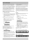
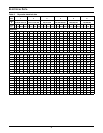
The minimum glycol temperature
to be supplied from the drycooler
determines whether the supply
and return lines should be insu-
lated to prevent condensation (see
Table 9).
Vents are required at system high
points to vent trapped air when
filling the system.
Since the system is not open to the
atmosphere, an expansion tank
must be provided for expansion
and contraction of the fluid with
temperature change. A relief
valve is also necessary.
A fill port is necessary for charg-
ing the system with glycol.
Depending on the complexity of the
system, various other devices may
be specified, such as pressure
gauges, valves, pumps and sensors.