


11
COMPONENT ASSEMBLY/INSTALLATION
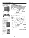
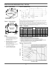
Leg Assembly
The legs are shipped loose and are
to be field mounted as shown with
the hardware provided.
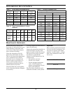
Rigging
Holes in the drycooler legs permit
lifting the unit. Spreader bars are
required. Four, 6 and 8 fan models
have additional lifting eyes.
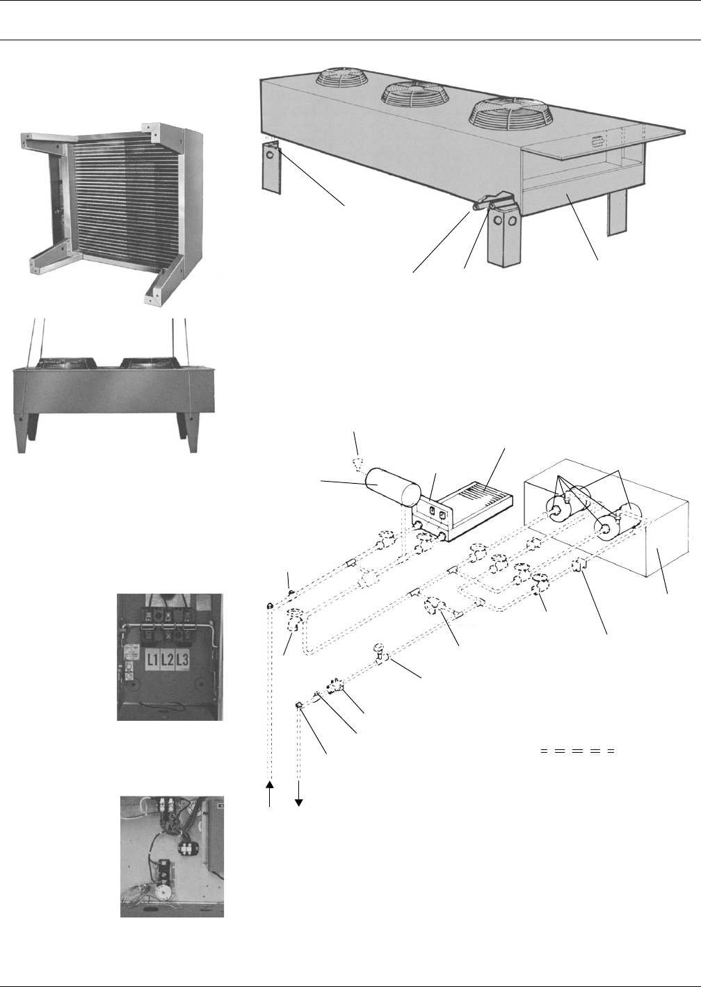
High Voltage Electrical
Connections
Line Voltage is
connected to the
terminal strip
or directly to
the factory sup-
plied locking
disconnect
(optional).
Check voltage
and compare to nameplate.
Low Voltage Electrical
Connections
A control inter-
lock between the
indoor and out-
door equipment
must be mini-
mum 16 ga. for
up to 75 ft. or not
to exceed 1 volt
drop in control
line.
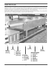
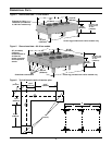
Typical rigging
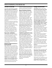
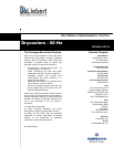
Figure 7 General arrangement diagram
Secure each leg to drycooler
frame at all four points shown
using hardware provided
Models 620 through 940 have 2 sets
of connections on end of unit
Electrical service
supply by others
Outlet
Inlet
Models 069-491
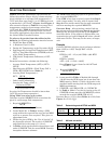
Pump
housing
Optional dual pump
system shown
Drycooler coil
Drycooler
electric box
Glycol
pumps
Fill*
Expansion
tank field
installed at
highest point
in system
Unions*
U
n
i
o
n
s
*
M
i
x
i
n
g
v
a
l
v
e
*
Hose
bib*
Pressure
port*
Air vents at top of risers*
Pressure port*
Flow regulating valve*
Flow switch supplied
with dual pump systems*
Check valves*
on dual pump
systems only
Gate or ball*
valve for
isolation (typ)
Gate or ball*
valve for bypass
Flow direction
* Components are not supplied by Liebert,
and all components shown may not be
necessary for system operation.
Field piping