


29
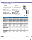
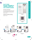
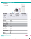
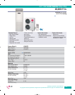
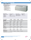
Floor Standing
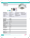
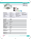
Ceiling Cassette
Type
A/C
A/C
A/C
A/C
System #
LF300CP
LF480CP
LC240CP
LC340CP
Indoor
230/208
230/208
230/208
230/208
BTUs
28,000
48,000
24,000
34,000
Rated
Amps
11.5/11.5
20.0/20.0
11.5/12.4
15.1/16.5
MCA*
17***
28.9***
17.3
27.5
MOP**
25***
50***
30
50
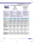
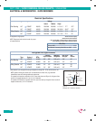
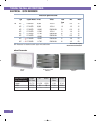
Electrical Specifications
Outdoor
230/208
230/208
230/208
230/208
Voltage
All equipment single phase.
NOTE: Please see local electrical codes for proper
wire specifications.
*Minimum Circuit Ampacity
**Maximum Overcurrent Protection
***Floor standing MCA + MOP calculated for indoor and outdoor
units connected to common breaker (Preferred method).
Wire Size
Minimum AWG 14-3
Indoor/Outdoor Connecting Cable Minimum AWG 14-3
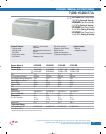
Floor Standing
Ceiling Cassette
Type
A/C
A/C
A/C
A/C
System #
LF300CP
LF480CP
LC240CP
LC340CP
Pipe size
Liquid Suction
3/8" 5/8"
3/8" 3/4"
1/4" 1/2"
1/4" 5/8"
BTUs
28,000
48,000
24,000
34,000
Additional
Refrigerant
0.32 oz./ft.
0.42 oz./ft.
0.32 oz./ft.
0.42 oz./ft.
Max. length
each pipe
100'
131'
100'
115'
Max.
elevation
66'
82'
50'
66'
Refrigerant Line Specifications
†
†
Each system is pre-charged with enough refrigerant to charge 25 ft. of line and the interior unit.
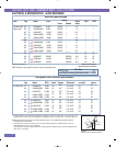
NOTE: Systems having the outdoor unit mounted above the indoor unit (e.g. basement
installations) have the following additional requirement:
For systems with maximum elevation of 25 ft. (see chart above and Figure A), refrigerant lines
must be oil trapped between 8 ft. and 16.4 ft. of elevation.
For systems with elevation of greater than 25 ft. (see chart above), refrigerant lines must be oil
trapped at least every 16.4 ft. of elevation.
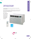
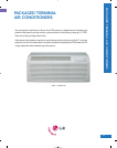
DUCT-FREE • FLOOR STANDING & CEILING CASSETTE • SINGLE ZONE
ELECTRICAL & REFRIGERATION • QUICK REFERENCE
25' maximum
8' minimum
16.4' maximum
OIL TRAP
INDOOR UNIT
OUTDOOR UNIT
Figure A.
Example: 25 ft. maximum elevation.