NOTE: DIAGRAMS & ILLUSTRATIONS ARE NOT TO SCALE.
5
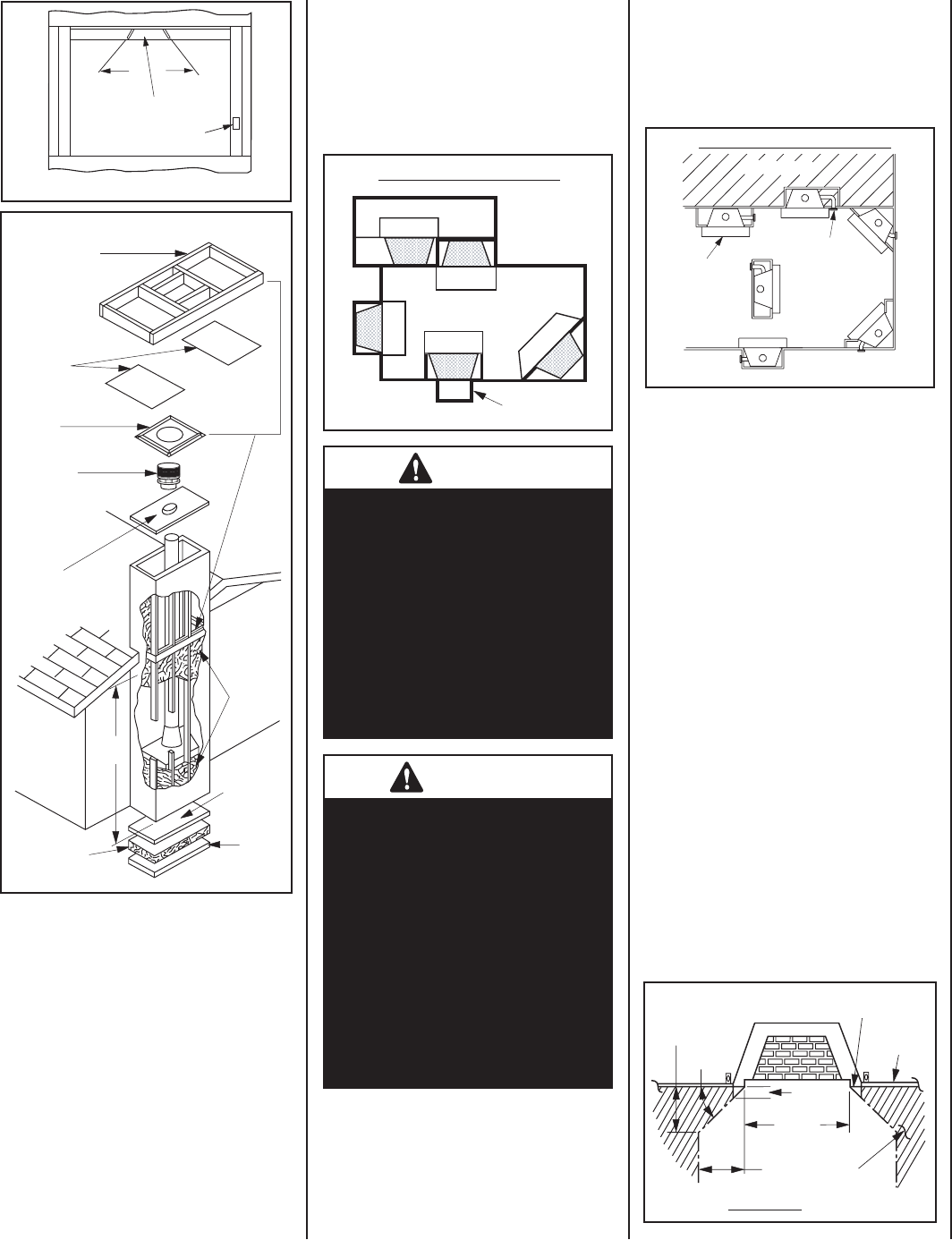
Figure 4
Insulate Joists
Same As Ceiling
Draft Stops
Firestop
CTDT
Termination
Note: Non-
Combustible
Chase
Flashing
Must Be
Used To
Cover
Chase
Opening
Optional
Insulation
In Outside
Walls Of
Chase
Solid
Continuous
Surface
Outside
Base
Insulation
(Thermal Barrier)
8'
Level
Chase Enclosure - Indoor Installation
Figure 3
Damper
Closed
Damper
Open
Lintel
Combustion Air Actuator
(when installed)
Hearth
Hearth
Optional
Outside Chase
LIVING SPACE
PATIO
Indoor Locations - Top View
Indoor Locations - Carefully consider the
position of the fi replace opening with re-
spect to the location of adjacent or nearby
stairwells, bath or kitchen exhaust fans
and/or return air registers for forced air
furnaces/air conditioners that could cause
a smoking fi replace condition if the house
is tightly insulated.
Figure 5
Outdoor Locations - Top View
Figure 6
When choosing a location, care must be taken
to avoid places where fl ooding or running
water may be a problem.
DO NOT place furniture or other items such
as plants or decorative objects within 60” of
the fi replace front face.
Figure 7 Clearances
Frame Surface Not to Be Covered
With Combustible Materials
12"
Wall
Covering
45°
12"
1"
Door
Opening
Safe
Zone
Restrictions for Outdoor installations:
• Outside Air Kit must be installed and
fully open on the outdoor installation. On
the indoor installation is optional unless
mandated by local building codes.
• Minimum chimney height for the outdoor in-
stallation is 7' 9" (one 4 foot pipe section).
• Minimum 2" chimney clearance is required
when system height is less than 15'.
• Only non-combustible materials are allowed
on the front face (Front Fireplace Frame) and
around the perimeter within 5” (full length of
top spacers) on the top and 1/2" on the sides
(see Figures 1, 51 & 52).
Combustible materials may project beyond the
sides of the fi replace opening as long as they
are kept within the shaded areas illustrated in
Figure 7.
CLEARANCES
Minimum clearance to combustibles for the
appliance is as follows: sides and back - 1” (25
mm), fl oor - 0” (0 mm), adjacent wall - 12” (305
mm), ceiling - 37 1/2” (953 mm).
Note: Clearance at the nailing tab is 0" (0mm)
(see Figure 25).
Note: Adjacent wall considerations are for
an adjacent wall on only a single side. Walls
should not be placed at minimum distance at
both sides of the fi replace.
CAUTION
To ensure that the outside air
kit remains open for an outdoor
installation, this fi replace should
not have a combustion air gate
control installed (OAKG-OD). If
this unit is installed indoors,
you must install the outside
combustion air cover provided or
an optional outside air kit gate
(OAKG-OD) before the fi replace
is framed in place.
ATTENTION
Assurer que les restes extérieurs
de kit d’air ouverts pour une instal-
lation extérieure, cette cheminée
n’ont pas une commande de porte
d’air de combustion a installé
(OAKG-OD). Si cette unité est
installée à l’intérieur, vous devez
installer la couverture extérieure
d’air de combustion fournie ou
une porte extérieure facultative
de kit d’air (OAKG-OD) avant
que la cheminée soit encadrée
en place.
LOCATION OF FIREPLACE
Carefully select the proper location for heat
circulation, aesthetics, chimney obstructions,
air inlet location and clearance to side wall(s).
With proper pre-planning, a slight adjustment
of a few inches can save considerable time and
expense later during construction and assembly.
See
Figures 5 & 6 for examples.
When locating the fi replace, consideration
must be given to combustibles and fi nal
fi nishing. See Figure 5 and confi ne the fi nal
location of combustible fi nish materials to
the "Safe Zone."
DO NOT permanently place furniture or other
items such as decorative pillows within 60"
of the fi replace front face.
Outdoor Locations - Carefully consider the
position of the fi replace opening with respect
to the location of adjacent or nearby stair-
wells, doors, windows, walk ways and over
hanging trees, patios and wires.
Optional
Hearth
Extension
Air Inlet (inlet
must be free of
any obstructions)


