NOTE: DIAGRAMS & ILLUSTRATIONS ARE NOT TO SCALE.
3
These fi replace systems are designed for installa-
tion in accordance with the National Fire Protec-
tion Standard for chimneys, fi replaces and solid
fuel burning appliances; NFPA 211-latest edition
and in accordance with codes such as the BOCA
Basic/National Codes, the Standard Mechanical
Code and the Uniform Building Codes.
Note: These fi replace systems are not diffi cult
to install. However, in the interest of safety, it is
recommended that the installer be a qualifi ed or
certifi ed “tradesman” familiar with commonly
accepted fi replace installation and safety tech-
niques as well as prevailing local codes.
INTRODUCTION
General Information
These fi replaces are traditional radiant heat
fi replaces with standard bar grates, optional
Outside Air Kits (required for outdoor installa-
tions) and optional Operable Bi-Fold Stainless
Outdoor Glass Doors and Weather Cover.
These appliances are approved for installation
indoors or outdoors.
Indoors: These appliances are approved
for installation in residential homes and
other buildings of conventional construction
including commercial, not in manufactured
homes(see Figure 5).
Outdoors: These appliances are approved for
installion against an outside wall of a house, or
as a freestanding fi replace on the porch, patio, or
located in the yard (see Figure 6). The Outdoor
Fireplace must be enclosed to prevent impact
damage to the outside of the fi replace. Build
an outside enclosure out of standard building
materials, being careful to maintain the minimum
air clearances specifi ed in these Installation
Instructions. When installing the fi replace as
a freestanding unit on your porch, patio or
backyard, it must also be enclosed to prevent
impact damage to the fi replace. However, the
enclosure must now be fi nished on all four (4)
sides. The exterior of the enclosure may be
fi nished in a textured plywood, a wood clapboard
siding, brick, or a cultured stone.
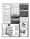
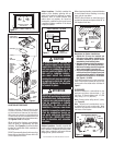
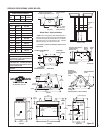
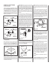
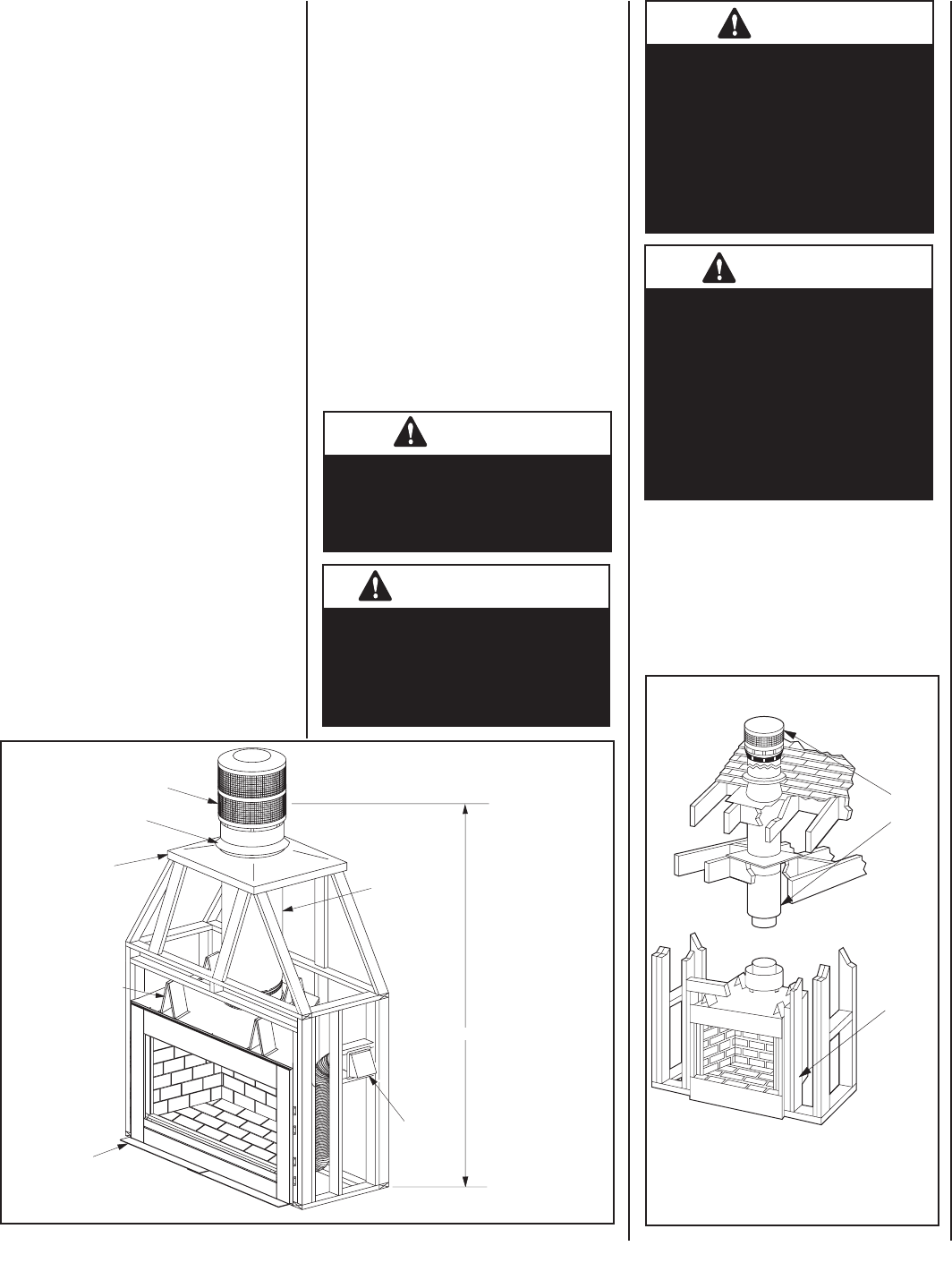
TYPICAL INSTALLATION - INDOORS
Outside
Combustion
Air Kit
(Optional)
Chimney and
Termination
Figure 2
Vinyl siding is not recommended for use
on the front of the fi replace due to the heat
the unit produces. This can cause the vinyl
siding to deteriorate.
Note: Illustrations shown refl ect “typical”
installations with nominal dimensions and
are for design and framing reference only.
Actual installations may vary due to individual
design preferences. However, always maintain
minimum clearances to combustible materials
and do not violate any specifi c installation
requirements.
These fi replaces have been tested and listed
by OMNI-Test Laboratories, Inc. (Report No.
116-F-37-2) to U.L. 127 (USA) and U.L.C.
S610 (Canada). These units are intended for
indoor and outdoor installations as specifi ed
in this manual.
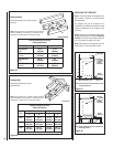
For installations in Canada, the chimney clear-
ance to combustibles must be 2 inches and
the Cold Climate Kit must be installed.
Outside Air Kit installa-
tion is optional unless
mandated by local build-
ing codes.
Note: Framing and fi replace shown as reference
only. It can differ according to design and local
building codes.
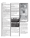
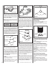
Chimney Section
(FTF8-48)
*Air Inlet
(Provided)
Flashing
(Locally
Fabricated)
Storm Collar
(FSC)
* Outside Air Kit (provided)
must be installed in
outdoor installation.
Note: Framing is shown as reference only. It can
differ according to design and local building codes.
7' 9" Min. (using one 4' section)
Termination (FTF8-CTDTM)
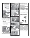
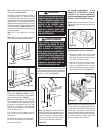
WARNING
Do not pack or fi ll required air
spaces with insulation or other
material. No material is allowed
in these areas.
AVERTISSEMENT
Ne remplissez pas les espaces
libres d’une matière isolante ou
de tout autre type de matériel.
Aucun matériel n’est permis
dans ces espaces vides.
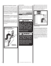
WARNING
If insulation is used, the fi replace
must not be placed directly against
it. Insulation or vapor barriers, if
used, must fi rst be covered with
gypsum board, plywood, particle
board or other material to assure
insulation and vapor barriers
remain in place.
AVERTISSEMENT
Si un isolant est utilisé, il ne doit
pas venir en contact avec le foyer.
L’isolant ou le coupe vapeurs, si
utilisée, doit d’abord être couvert
d’un panneau de gypse, contre-
plaqué, panneau de particules ou
d’un autre matériel pour s’assurer
que l’isolant et le coupe vapeurs
demeurent en place.
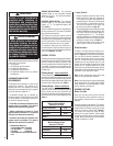
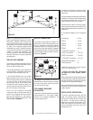
TYPICAL INSTALLATION - OUTDOORS
Figure 1
Notes:
• Framing is shown as
reference only. It can differ
according to design and
local building codes.
• Fireplace is shown for
illustration purposes only.
It may differ from actual
model.
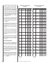
Use Only Non-Combus-
tible Materials From Top
Of Spacers Down (5"
Min.) And Within 1/2"
Min. To Side Frame.
Outdoor fi replace system
less than 15 feet height
must have a chimney
clearance of 2” air
space to insulation and
construction materials
and be a minimum of 10
feet away from a building
or combustible structure.
If installed closer than
10 feet, the 10 foot rule
applies (see ten foot rule
summary on Page 15).
Metal Safety Strips
And Hearth Extension
Required When Installed
On Combustible Floor Or
In Proximity To Combus-
tible Floor/Covering.


