


16
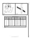
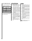
Fireplace
Model
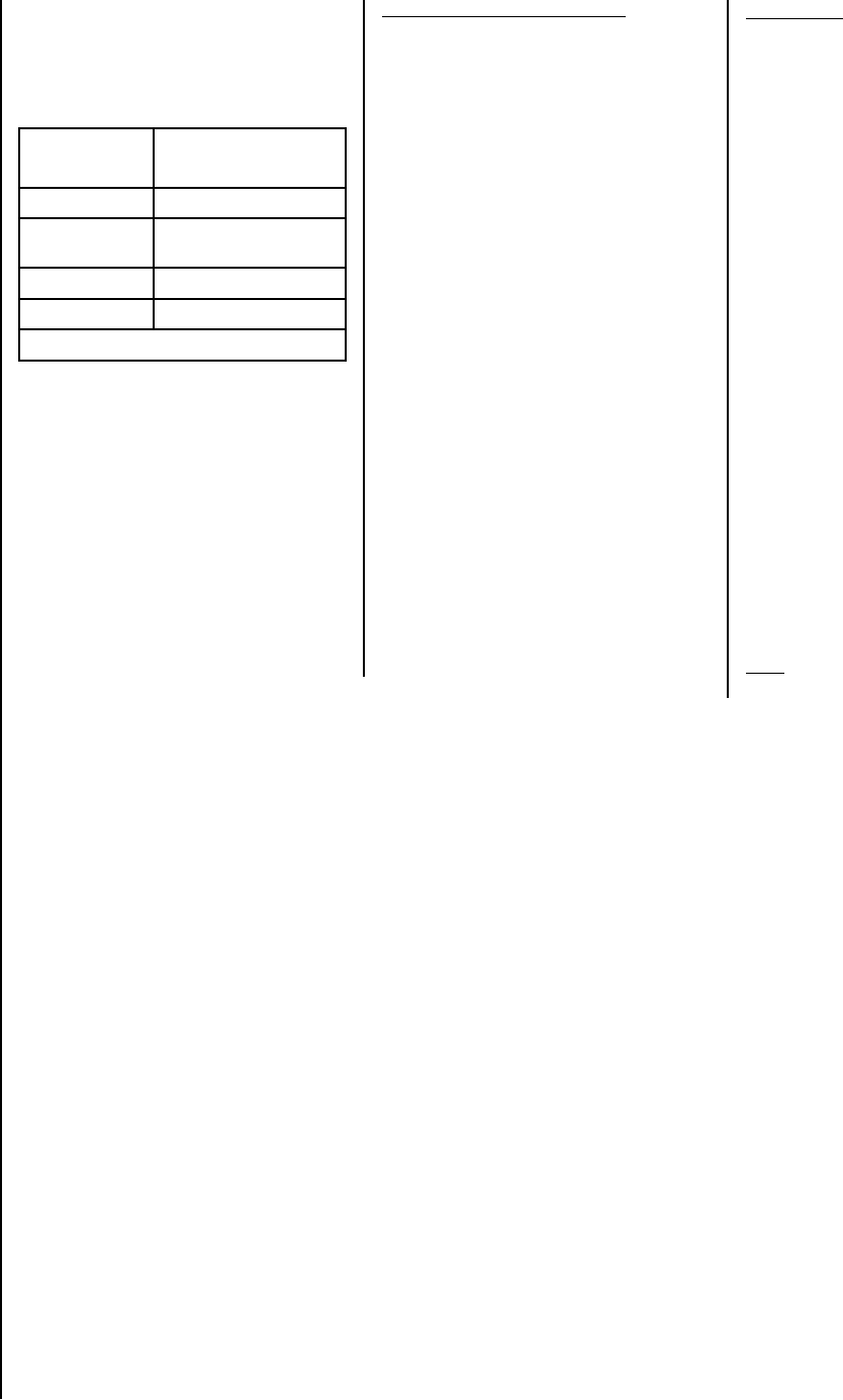
ME43BK SP
Chimney Model 8" ASHT+/S-2100+/AC
Vertical
Installation
15 feet (4.57 m)
Two (2) Elbows 18 feet (5.49 m)
Four (4) Elbows 20 feet (6.10 m)
Table 4
After reaching the location requiring the
elbow, proceed as follows:
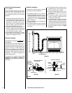
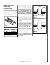
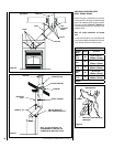
OFFSET CHIMNEY INSTALLATION
The minimum chimney height (including
the fireplace) when using elbows is:
AC chimney
1. Install the first elbow. Turn it in the
required direction. To lock it in place,
turn 1/8 of a turn. Fasten the straps at-
tached to the elbow to the surrounding
framing using nails or drywall screws
(Figure 20).
2. Install the necessary chimney lengths
to achieve the required offset. Lock the
chimney lengths together. If penetrat-
ing a wall, use a wall radiation shield
(Figure 22).
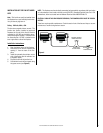
3. Use another elbow to turn the chimney
vertically. Lock it to the chimney.
Fasten the straps attached to the elbow
to the surrounding framing using nails
or drywall screws.
4. Use a plumb-bob to line up the center
of the hole. Cut a hole for the chim-
ney in the ceiling. Frame this hole as
described previously.
5. From below, install a radiation shield
(see Figure 17B).
6. Continue with the regular installa-
tion.
Note: An AC8SB starting section must be
used before installing an elbow.
ASHT+ and S2100+ Chimneys
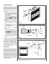
1. Install the first elbow. Turn it in
the required direction. Fasten it to
the chimney with the three (3) 1/2"
(12mm) metal screws provided.
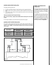
2. Install the necessary lengths to achieve
the required offset. Lock the chimney
lengths together: it is recommended
to use three (3) 1/2" (12mm) screws.
If the offset length is made of two (2)
chimney lengths use an offset support
halfway up the offset. If penetrating
a wall, install a wall radiation shield
(see Figure 22).
3. Use another elbow to turn the chimney
vertically. Secure the elbow, using
three (3) 1/2" (12mm) screws.
4. Use a plumb-bob to line up the center
of the hole. Cut a hole for the chim-
ney in the ceiling. Frame this hole as
described previously (see Page 12).
5. From below, install a radiation shield
(Figure 17A).
6. A support (ST+ or SO+) must be used
on the first 15’ section (5 m).
7. Continue with the regular installa-
tion.