


—6—
2.1 MECHANICAL PARTS
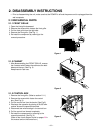
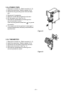
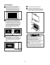
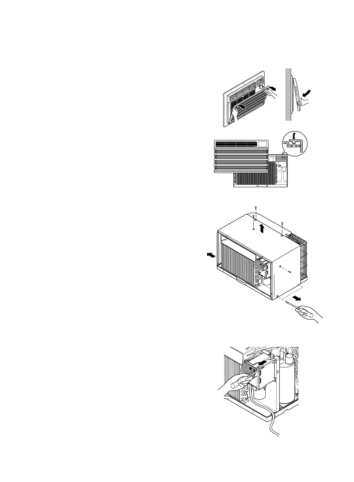
2.1.1 FRONT GRILLE
1. Open the inlet grille downward.
2. Remove the screw which fastens the front grille.
3. Pull the front grille from the right side.
4. Remove the front grille. (See Fig. 1)
5. Re-install the component by referring to the
removal procedure.
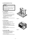
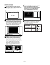
2.1.2 CABINET
1. After disassembling the FRONT GRILLE, remove
the 6 screws which fasten the cabinet at the both
sides and the top. (See Fig. 2)
Keep these for later use.
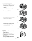
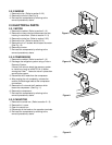
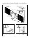
2.1.3 CONTROL BOX
1. Remove the front grille. (Refer to section 2.1.1)
2. Remove the screw which fasten the control
box. (See Fig. 3)
3. Pull the control box from the barrier.(See Fig.3)
4. Discharge the capacitor by placing a 20,000 ohm
resistor across the capacitor terminals.
5. Disconnect two wire housings in the control box.
6. Pull the control box forward completely.
7. Re-install the components by referring to the
removal procedure. (See Fig. 3)
(Refer to the circuit diagram found on pages 26 in
this manual and on the control box.)
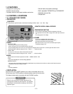
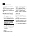
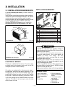
2. DISASSEMBLY INSTRUCTIONS
— Prior to disassembling the unit, make sure that the POWER is off and the power cord is unplugged from the
wall receptacle.
M
O
D
E
T
I
M
E
R
P
O
W
E
R
FAN
SPEED
F
a
n
E
n
e
r
g
y
S
a
v
e
r
C
o
o
l
T
i
m
e
r
TEMP
'
F
F
1
L
O
W
F2
ME
D
F
3
H
IG
H
Figure 1
Figure 2
MODE
TIMER
POWER
F
A
N
S
P
E
E
D
F
a
n
Energy
Saver
C
o
o
l
T
im
e
r
T
E
M
P
'
F
F
1
L
O
W
F
2
M
E
D
F
3
H
I
G
H
M
O
D
E
T
I
M
E
R
P
O
W
E
R
F
A
N
S
PEE
D
Fa
n
E
n
e
r
g
y
S
a
v
e
r
C
o
ol
Tim
er
T
E
MP
'
F
F
1
L
O
W
F
2
M
E
D
F
3
H
I
G
H
MODETIMER POWER
FAN
SPEED
Fan
Energy
Saver
Cool
Timer
TEMP
'
F
F1 LOW
F2 MED
F3 HIGH
Figure 3