


LG-10 thru LG-30 - User Manual Electro-Steam Generator Corp.
4 of 33
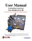
1.) INSTALLATION INSTRUCTIONS
LITTLE GIANT “LG-SERIES”
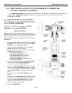
The Electro-Steam Generator design consists essentially of a high pressure chamber filled with water
that is heated by one or more submerged resistance type electric heating elements. Automatic controls
are provided to maintain the pre-set operating pressure and water level. Safety features include:
automatic low-water cutoff (manual low-water reset optional), dual pressure controls, safety valve, and
visible water level gauge. All of our generators are built in accordance with A.S.M.E. Miniature Boiler
Code and are individually inspected and stamped by an Authorized National Board Insurance Inspector.
IMPORTANT – READ ALL INSTRUCTIONS BEFORE OPERATING
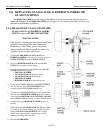
Important – Set unit perfectly level, and as close as possible to the steam vessel or appliance it
will operate. For generator measurements, refer to Installation Data Drawing attached. For
interpretation of numbered items, refer to Parts Legend Drawing attached. NOTE: Ambient
temperature around this unit must not exceed 105°F.
CONNECTIONS:
Periodically check all plumbing and electrical connections for tightness; this should also be done
before initial start-up.
ELECTRICAL:
This generator must be connected to a disconnect switch protected by fuses or
circuit breakers with the proper size wire by a licensed electrician in
accordance with N.E.C. and your local codes – Voltage, KW, and Phase
requirement are marked on the nameplate.
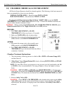
WATER SUPPLY:
Connect city water line to Y-Strainer (#6).
Purity: NOT to exceed 26,000 OHMS per CM
Temperature Range: 32°F – 140°F or 0°C – 60°C.
Pressure Range: 20PSI – 150PSI.
*CAUTION: The Pump (#8) requires clean tap water. If the water is not free of foreign matter, a 5
micron cartridge filter should be installed in the water supply line.
STEAM OUTLET:
Connect Steam Outlet Valve (#16) to piece of equipment, vessel, room, or area to be operated by
the Electro Steam Generator.
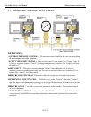
SAFETY VALVE & DRAIN:
Separately route the Safety Valve (#18) & Drain (#23) to a high temperature drain *NO PVC.
Discharging pipe of the Safety Valve (#18) should never be smaller than the valve outlet and
should be rigidly supported, placing no weight on the safety valve itself. If equipped with
Motorized Auto-Flush & Drain “MAFD” (#20), it should be routed with the Drain (#23).