


BEKOMAT 21, 21 PRO12
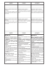
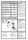
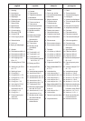
Electrical data • Características eléctricas
Caractéristiques électriques • Características eléctricas
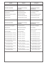
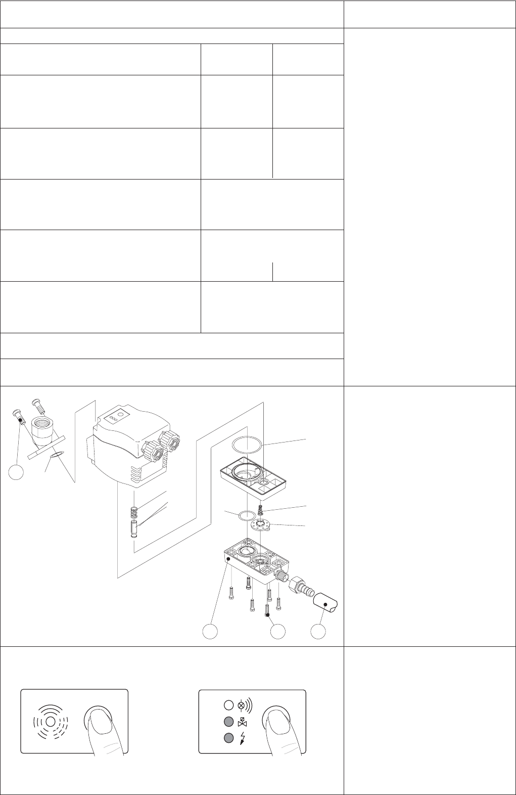
Maintenance • Mantenimiento • Entretien • Manutenção
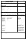
Max. power input
Potencia máxima absorbida
Consommation maximale et fusibles
Potência máx. absorvida e fusível recomendado
Supply voltage (see type plate)
Tensión de entrada (ver etiqueta identificativa)
Alimentation électrique (voir plaque sign.)
Tensão de rede (ver placa indicadora)
recommanded cable jacket diameter
Diámetro exterior del cable recomendado
diamètre recommandé pour la gaine du câble
Diâmetro recomendado do invólucro de cabo
Cable cross-section and fuse protection
Sección de cable y fusible
Section des fils et fusibles
Secção do cabo e fusível recomendado
Contact loading
Carga del contacto
Pouvoir de coupure
Carga de contato
BEKOMAT 21 BEKOMAT 21 PRO
*) time lag / lento / temporisée / mittelträge
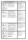
english
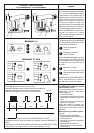
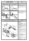
Functional test of BEKOMAT device:
• Briefly press test button.
! Valve opens for condensate
discharge.
BEKOMAT 21 PRO:
Checking of alarm signal:
• Shut off condensate inflow.
• Press test button for at least 1 min.
! Red LED flashes
! Alarm signal is being relayed
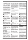
BEKOMAT 21 PRO
Potential-free contact
The alarm signal can be relayed via a
potential-free contact. The changeo-
ver contact can be operated, e.g., in
the fail-safe mode.
When operating voltage is being app-
lied and the BEKOMAT device is
functioning correctly, the alarm relay
is energized. The contact element
(N.O.– COM).
When there is no operating voltage or
in the case of a fault signal, the alarm
relay drops out. The contact element
is open (alarm).
Externernal Test button (optional)
Here, the normal test button function
has been extended for additional use
outside the BEKOMAT unit. This
makes it possible to discharge any
condensate in the unit by remote
control, if required. When the external
contact closes, the valve will open.
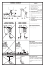
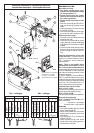
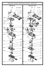
Before maintenance work always
ensure that the device is:
• pressureless and
• de-energized.
Maintenance recommendation:
• Remove 2 pan head screws (1) and
lift off BEKOMAT. The elbow adap-
tor stays in place.
• Disconnect discharge hose (2).
• Turn the 6 pan head screws (3) until
heads are level with the outer edge
and take off diaphragm seat (4).
• Replace wearing parts
• Reassemble BEKOMAT unit in re-
verse order.
TEST
Alarm
Valve
Power
TEST
Power
Alarm
Valve
**) min. internal resistance of
voltage source Ri> 12 Ohm
x
x
x
x
x
x
x
x
x
3 2
1
4
24 Vdc
P < 2,0 W
U
0
= 24Vdc
-10/+25%
P < 2,0 VA
Uac = ... ±10%
50 – 60 Hz
3 x 0,75 mm² / 5 x 0,25 mm²
< 250 Vac / < 1,0 A
> 5 Vdc / > 10 mA
230/110/24/
... Vac
0,5 A *)
100 mA *) **)
max. ø 10 mm
Set of wearing parts ( x )
BEKOMAT 21 / 21 PRO XE KA21 101