


BEKOMAT 21, 21 PRO10
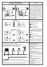
Electrical installation • Instalación eléctrica
Installation électrique • Instalação eléctrica
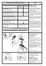
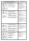
phase
neutral
earth/ground
4 3 2
L
N
PE
0V (+24 Vdc)
+24 Vdc (0V)
external test
--
0V
+24 Vdc
±24
±24
IN1
0TV
0V
+24
KL1
KL4
KL2 KL2
3 2 1
6 5 4 3 2 1
3 2 1
0V
IN1
KL5
1 2
normally
closed
common
normally open
0V
external test
normally closed
common
normally open
9
10
KL 2
5
4
2
3
7
8
9
6
10
1
11
12
KL 4
KL 1
KL 2
KL 5
Vdc - voltage
Vac - voltages
(optional)
(optional with 2 or 6 contacts
opcional de 2 ó 6 poles
en option, 2 ou 6 pôles
opcional bibolar ou 6 poles)
910 109
BEKOMAT 21 PRO
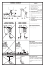
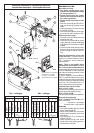
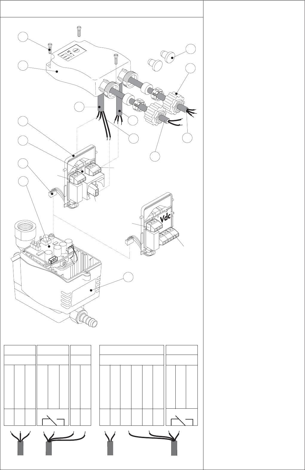
Note before wiring:
• The mains voltage must corre-
spond to the permissible voltage
on the type plate (1)!
• Please ensure that the instal-
lation is carried out according to
the valid regulations.
• Please assign terminals as indi-
cated!
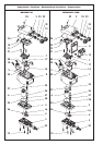
• Remove screws (5) and lift off hou-
sing top (4) paying attention to the
cable.
• Unplug connector (7) from terminal
on control PCB (8).
• Fit board holder (2) with power sup-
ply board into the housing top (4).
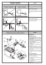
Connect power supply
• Unscrew union nut (6) and remove
blanking disk (12)
• Guide a 3-core cable (9) for power
supply through screwed cable fitting
and connect to board terminal KL1
or KL4.
• Guide a 5-pole cable (10) for poten-
tial-free contact and for external test
button through screwed cable fit-
ting.
Terminal assignment in the case
of Vac devices: L = phase conductor
(black), N = neutral conductor (blue),
PE = protective earth conductor
(green/yellow)
Note: There is no metallic isola-
tion between terminals KL4.1-6 or
KL 5.1-2 and the condensate area.
In the case of 24 Vdc operation, do not
connect +24 Vdc to frame because
the internal housing potential of the
device is negative.
*) When supplying several BEKO-
MAT 21 units simultaneosusly from a
single 24 Vdc source we recommend:
connect operating voltage preferably
to KL4.4 + KL4.5 instead of KL4.1 +
KL4.2 while observing the polarity.
Potential-free alarm contact
KL2.3-2 N.C.–COM:
Contact closed during malfunction or
power failure (fail-safe principle).
KL2.1-2 N.O.–COM:
Contact closed during normal operation.
External test (optional)
KL5.1-2 oder KL4.2-4 0V–IN1: Con-
tacts connected
= test active = discharge
Contacts open = test inactive
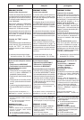
Assembly
• Pull cables (9+10) tight and screw
down cable fittings (6)
• Move board holder (2) with power
supply board upwards (must click
into place).
• Plug connector (7) to terminal on
control PCB (8).
• Slide housing top (4) with board
holder (2) into the guiding grooves.
• Tighten the screws (5).
*)