


Page 4
Lighting Information and Operation
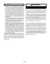
WARNING
If you do not follow these instructions exactly, a fire
or explosion may result causing property damage,
personal injury or loss of life.
BEFORE LIGHTING smell all around the appliance area
for gas. Be sure to smell next to the floor because some
gas is heavier than air and will settle on the floor.
Placing Furnace Into Operation
G24MCE units are equipped with an electronic ignition sysĆ
tem. Do not
attempt to manually light burners on these furĆ
naces. Each time the thermostat calls for heat, the burner
will automatically light.
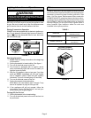
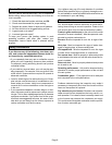
THERMOSTATS
FIGURE 1
Gas Valve Operation
1 - STOP! Read the safety information at the beginning
of this section.
2 - Set the thermostat to lowest setting. See figure 1.
3 - Turn off all electrical power to the unit.
4 - This furnace Is equipped with an ignition device
which automatically lights the burner. Do not try to
light the burner by hand.
5 - Wait five (5) minutes to clear out any gas. If you then
smell gas, STOP! Immediately call your gas supplier
from a neighbor's phone. Follow the gas supplier's
instructions. If you do not smell gas go to next step.
6- Turn on all electrical power to the unit.
7- Set the thermostat to desired setting.
NOTE-When unit is first started, steps 1 through 7 may
need to be repeated to purge air from gas line.
8- If the appliance still will not operate, follow the
instructions Turning Off Gas To Unit" and call your
service technician or gas supplier.
Turning Off Gas To Unit
1 - Set the thermostat to the lowest setting.
2 - Turn off all electrical power to the unit if service is to
be performed.
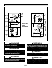
Filters
G24MCE series units are equipped with external filters
which should be inspected monthly and replaced when
necessary to assure proper furnace operation. See
table 1 for filter sizes. Replacement filters used with
G24MCE-40/60/75 units must have a minimum velocĆ
ity rating of 2 m/s (400 FPM). Replacement filters used
with G24MCE-100/120/140 units require a minimum
velocity rating of 3.2 m/s (625 FPM). Figures 2 and 3
show possible filter locations when the units are
installed in the upflow position.
TABLE 1
MODEL NO.
FILTER SIZE -
millimeters (inches)
G24MCE-45/60/75
406X508X25
(16 X 20 X 1)
G24MCE-100/120/140
508X508X25
(20 X 20 X 1)
UPFLOW FURNACE
BOTTOM RETURN AIR
FIGURE 2