


Page 4
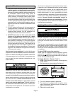
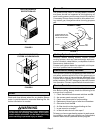
6 - White Rodgers 36E Gas Valve - Switch gas valve lever
to OFF. See figure 2.
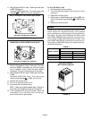
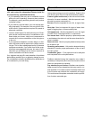
Honeywell VR8205 Gas Valve - Turn knob on gas valve
clockwise
to OFF. Do not force. See figure 3.
WHITE RODGERS 36E SERIES GAS VALVE
GAS VALVE SHOWN IN OFF POSITION
FIGURE 2
ON
OFF
HONEYWELL VR8205 SERIES GAS VALVE
GAS VALVE SHOWN IN OFF POSITION
FIGURE 3
7 - Wait five (5) minutes to clear out any gas. If you then
smell gas, STOP! Immediately call your gas supplier
from a neighbor's phone. Follow the gas supplier's
instructions. If you do not smell gas go to next step.
8 - White Rodgers 36E Gas Valve - Switch gas valve lever
to ON.
Honeywell VR8205 Gas Valve - Turn knob on gas
valve counterclockwise
to ON. Do not force.
9 - Replace the access panel.
10 - Turn on all electrical power to unit.
11 - Set thermostat to desired setting.
NOTE – When unit is initially started, steps 1 through 11
may need to be repeated to purge air from gas line.
12 - If the appliance still will not operate, follow the
instructions To Turn Off Gas To Unit" and call your
service technician or gas supplier.
To Turn Off Gas To Unit
1 - Set thermostat to lowest setting.
2 - Turn off all electrical power to unit if service is to be
performed.
3 - Remove the access panel.
4 - Switch lever on White Rodgers gas valve to OFF; turn
knob on Honeywell valve clockwise
to OFF. Do not
force.
5 - Replace the access panel.
Filters
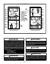
G24M series units are equipped with external filters
which should be inspected monthly and replaced
when necessary to assure proper furnace operation.
See table 1 for filter sizes. Replacement filters used
with G24M-40/60/75 units must have a minimum veĆ
locity rating of 400 FPM. Replacement filters used
with G24M-100/120/140 units require a minimum veĆ
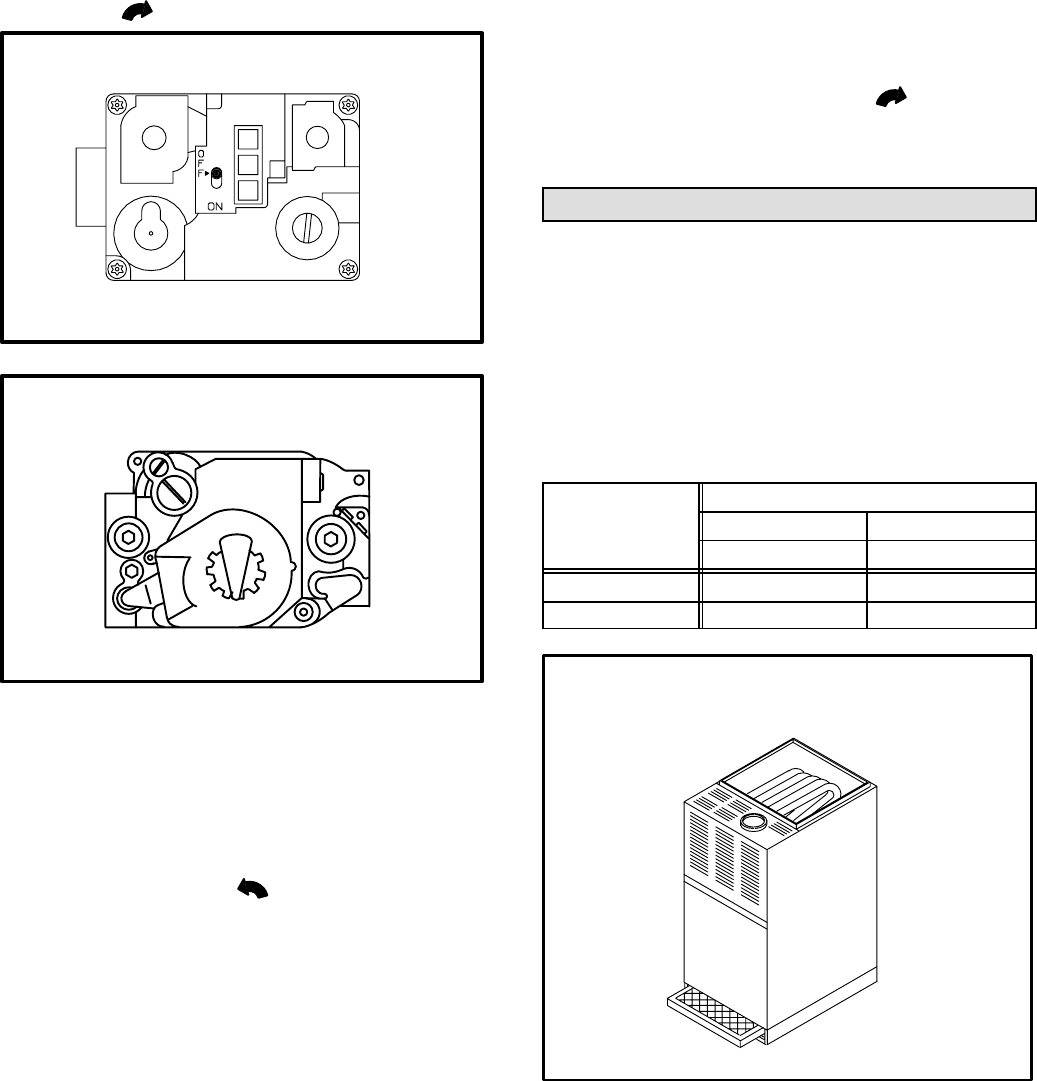
locity rating of 625 FPM. Figures 4, 5, and 6 show posĆ
sible filter locations.
TABLE 1
FILTER SIZE
MODEL NUMBER
UPFLOW DOWNFLOW
1 FILTER 2 FILTERS
G24M-45/60/75 16 in. X 20 in. X 1 in. 16 in. X 20 in. X 1 in.
G24M-100/120/140 20 in. X 20 in. X 1 in. 16 in. X 20 in. X 1 in.
UPFLOW FURNACE
BOTTOM RETURN AIR
FIGURE 4