


INSTALLATION
See Pipe Manufacturers Instructions For Installation Requirements Of Venting Components And Vent Clearances.
PAGE 13
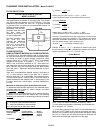
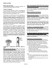
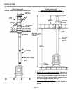
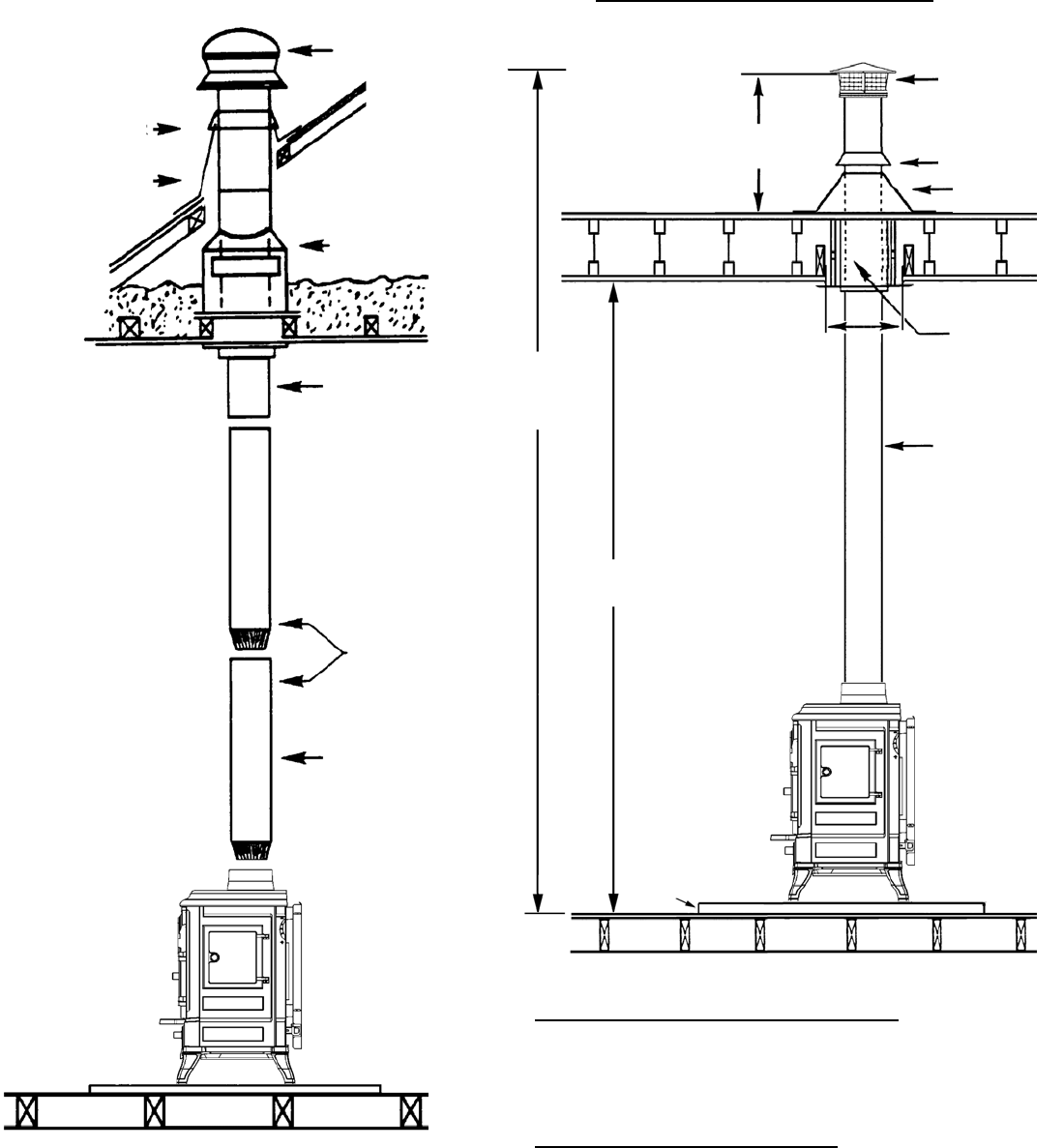
SINGLE WALL PIPE
Using 6” Diameter Single Wall Connector Pipe
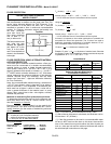
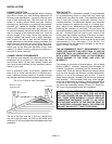
DOUBLE WALL PIPE
(Approved for Model CI2000HT Only)
Using 6” Diameter Type L-Vent Connector Pipe
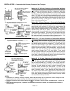
IMPORTANT NOTES:
• Minimize the use of elbows (30°, 45° or 90°) - Offsets in the
venting system are very restrictive and will inhibit the draft
(i.e. You will lose approximately 5 feet of effective draft for
every 90 degrees of direction change). This appliance re-
quires 12 to 15 feet of effective draft for optimum perform-
ance (see Draft Requirements on page 12).
• First section of pipe must be vertical - Use as much straight
vertical pipe directly above the appliance as possible be-
fore using an elbow (a 2’ to 3’ initial vertical rise is sug-
gested).
Chimney
Termination
Cap
Ceiling Support
Assembly
Storm
Collar
Roof
Flashing
Slip
Adapter
Minimum of 12-15' o
f
Flue to achieve
a
stable draft
.
Chimney
Connector
6" x 24" 24-gag
e
black steel or 26 gag
e
blued steel single wall
pipe
7 Feet
Minimum
DVL Close
Clearance
Connector
Pipe
Floor
Protector
Support
Box
3 Feet
Minimum
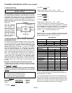
Termination
Cap with
Spark Arrestor
Storm Collar
Flashing