


Page 24
506728−01
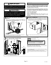
3. Inspect all factory− and field−installed wiring for loose
connections.
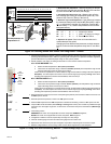
4. Open the high side manifold gauge valve and weigh in
liquid refrigerant. Use figure 20 to calculate the correct
weigh−in charge.
5. Close manifold gauge valves.
6. Monitor the system to determine the amount of
moisture remaining in the oil. It may be necessary to
replace the bi−flow filter drier several times to achieve
the required dryness level. If system dryness is not
verified, the compressor will fail in the future.
7. Continue to Optimizing System Refrigerant Charge
on page 25 to optimize the system charge using
subcooling method.
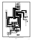
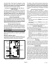
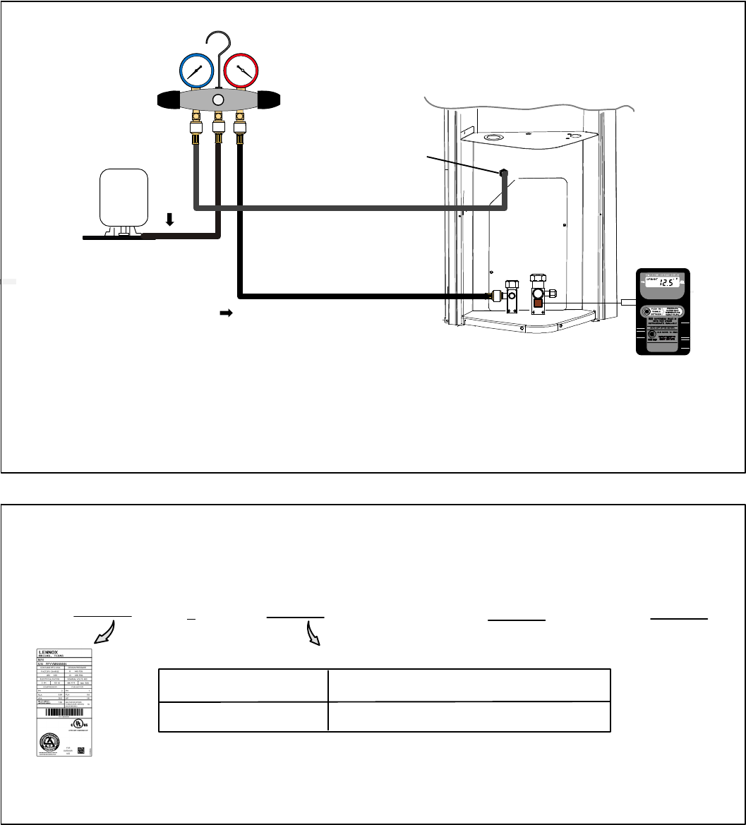
TO LIQUID
LINE SERVICE
VALVE
DIGITAL SCALE
REFRIGERANT
TANK
TEMPERATURE
SENSOR
(LIQUID LINE)
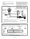
MANIFOLD GAUGE SET
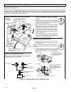
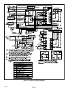
A Close manifold gauge set valves and connect the center hose to a cylinder of HFC−410A. Set
for liquid phase charging.
B Connect the manifold gauge set’s low pressure side to the true suction port.
C Connect the manifold gauge set’s high pressure side to the liquid line service port.
D Position temperature sensor on liquid line near liquid line service port (use only for subcooling
method).
CHARGE IN
LIQUID PHASE
CONNECTIONS FOR OPTIMIZING SYSTEM CHARGE
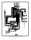
GAUGE SET
A
C
D
LOW
HIGH
B
TRUE SUCTION PORT
CONNECTION
NOTE Ċ Refrigerant
tank should be turned
right−side−up to deliver
vapor during charge
optimizing procedure.
HFC−410A
NOTE Ċ For simplify the illustration,
the line set is not shown connected to
service valves.
Figure 19. Typical Gauge Set Connections for Initial Weight−in Charge or Optimizing System Charge
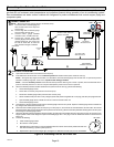
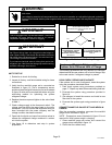
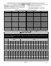
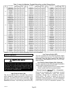
LIQUID LINE SET DIAMETER
OUNCES PER 5 FEET (GRAMS PER 1.5 METERS)
ADJUST FROM 15 FEET (4.6 METERS) LINE SET*
3/8" (9.5 MM)
3 OUNCE PER 5’ (85 GRAMS PER 1.5 M)
*If line length is greater than 15 feet (4.6 meters), add this amount. If line length
is less than 15 feet (4.6 meters), subtract this amount.
Refrigerant Charge per Line Set Length
NOTE Ċ The above nameplate is for illustration purposes only. Go to actual nameplate on outdoor unit for charge information.
NOTE Ċ Insulate liquid line when it is routed through areas where the surrounding ambient temperature could become higher than the temperature
of the liquid line or when pressure drop is equal to or greater than 20 psig.
CALCULATING SYSTEM CHARGE FOR OUTDOOR UNIT VOID OF CHARGE
If the system is void of refrigerant, first, locate and repair any leaks and then weigh in the refrigerant charge into the unit. To calculate the total refriger-
ant charge:
Amount specified on
nameplate
Adjust amount. for variation in line set
length listed on line set length table below.
Additional charge specified per
match indoor air handler or coil
listed in table 5.
Total Charge
+
+
=
Figure 20. Using HFC−410A Weigh In Method